5
4
3
2
1
A
B
C
DEF
G
H
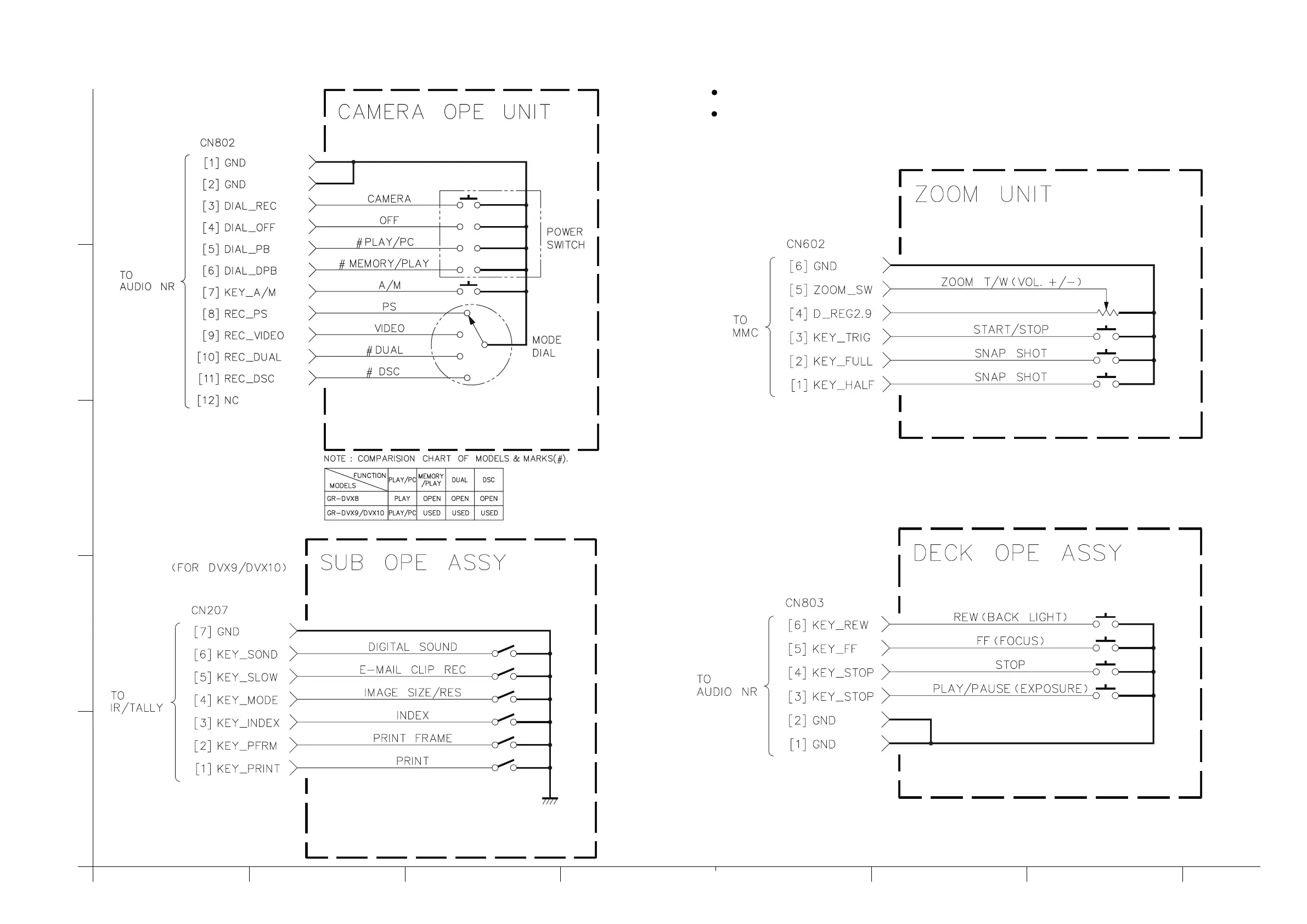
4.31 CAMERA OPE UNIT, SUB OPE ASSY, ZOOM UNIT AND DECK OPE ASSY SCHEMATIC DIAGRAMS
4-63 4-64
— SUB OPE ASSY —
— DECK OPE ASSY —
— ZOOM UNIT —
— CAMERA OPE UNIT —
NOTES: For the destination of each signal and further line connections that are cut off from
this diagram, refer to “4.1 BOARD INTERCONNECTIONS”.
The schematic diagram is only for reference. Avoid replacing individual parts.
Replace the entire unit only.