1-4
1
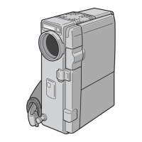
DECK OPE ASSY Fig.1-3-1 2(S1), (L1) –
✩CN A
2
FRONT COVER (S2a), (S2b), 2(S2c), (S2d) –
ASSY (S2e), (S2f), (L2)
COVER (DV), STUD (HOOK)
✩CN B
3
U. CASE ASSY Fig. 1-3-2a 2(S3a), (S3b), 2(S3c), 3(S3d) NOTE3a
(Inc. MONITOR LOCK (MONITOR) NOTE3b
ASSY) ✩CN C, D, E
(CN C : DVX9,10 ONLY)
4
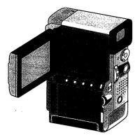
MONITOR ASSY Fig. 1-3-2b (S4a), (S4b) NOTE4
5
BASE ASSY Fig. 1-3-3 (S5a), (S5b), (S5c) –
✩CN F
6
L. CASE ASSY Fig. 1-3-4 6(S6) NOTE6a
✩CN G, H, J, K, L, M, N NOTE6b
(CN G, K : DVX9,10 ONLY) NOTE6c
7
OP BLOCK ASSY Fig. 1-3-5 (S7) NOTE7a
NOTE7b
8
STROBE ASSY Fig. 1-3-6 (S8) NOTE8
(DVX9,10 ONLY)
9
MIC Fig. 1-3-7 (L9) NOTE9
✩CN O
0
E VF ASSY Fig. 1-3-8 (S0a), (S0b), (S0c), 2(L0a) NOTE0a
(L0b), BRACKET (TOP) NOTE0b
✩CN P NOTE0c
-
AUDIO VF Fig. 1-3-9 2(S-a), (S-b), 2(L-) –
BOARD ASSY ✩CN Q
=
MDA BOARD Fig. 1-3-10 (S=) NOTE=a
ASSY ✩CN R, S, T, U, V NOTE=b
~
MAIN BOARD (S~a), (S~b), (L~) NOTE~
ASSY SHIELD PLATE
✩CN W, X
!
MECHANISM 2(S!a), (S!b), 2(L!) –
ASSY BRACKET (MECHA)
1.3.2 Disassembly method (I)
STEP
PART Fig No. POINT NOTE
No.
Table 1-3-2
CONN.
CONNECTOR Pin No.
No.
A DECK OPE ASSY – AUDIO VF CN803 6
B JACK CN901 MAIN CN1008 16
C MDA CN207 SUB OPE ASSY – 7
D MAIN CN1004 W/B SENS – 3
E MAIN CN1007 MONITOR CN7501 45/39
F MAIN CN1014 MULTI PIN – 33
G MDA CN208 MMC CN601 14
H MDA CN205 OP BLOCK ASSY – 24
J MAIN CN1009 EJECT SW – 2
K MAIN CN1011 STROBE CN6501 12
L MAIN CN1003 CCD – 20
M MAIN CN1016 AUDIO VF CN801 100
N MAIN CN1017 CCD CN5203 2
O AUDIO VF CN804 MIC – 5
P VF BL CN501 AUDIO VF CN805 20
Q AUDIO VF CN802 CAMERA OPE UNIT – 12
R MAIN CN1002 MDA CN206 80
S MDA CN202 DRUM MOTOR – 11
T MDA CN201 LOADING MOTOTR – 6
U MDA CN203 CAPSTAN MOTOR – 18
V MDA CN204 SENSOR – 15
W MAIN CN1005 ROTARY ENCODER – 6
X MAIN CN1001 HEAD – 8
Table 1-3-3
Note3a:
When removing, be careful not to break the wire.
Note3b:
When removing, be careful not to damage any part.
On removing, slightly open the front side so as to
shift it from the frame.
Note4:
For disassembling method, refer to Fig. 1-4-1.
Note6a:
When removing, be careful not to break the wire.
Note6b:
Remove the board assembly (MAIN/MDA) and
mechanism assembly together.
Note6c:
When installing, arrange the wire between the OP
block assembly and VF assembly.
Note7a:
When removing, be careful neither to break the wire
nor to damage any part.
Note7b:
For disassembling method, refer to Fig. 1-6-1.
Note8:
Be careful not to get an electric shock during the
work.
Note9:
When reassembling, carefully arrange the wire.
Note0a:
When disassembling/reassembling, be careful not
to damage any part.
Note0b:
When reassembling, set the bracket (top) as the VF
unit is pulled out, and secure the installation in order
of (L
0
a) and (L
0
b).
Note0c:
For disassembling method, refer to Fig. 1-5-1.
Note=a:
When disconnecting the connector, carefully handle
the FPC on the top of the connector.
Note=b:
Disconnect the connector
V
last, because it is
positioned inside.
Note~:
When reassembling, carefully locate the FPC so
that it is sandwiched between the mechanism
assembly and MAIN board assembly.