2-2
Motor
DC3V
EJECT mode
Back side of deck
2.2 DISASSEMBLY/ASSEMBLY OF MECHANISM
ASSEMBLY
2.2.1 General statement
The mechanism should generally be disassembled/assem-
bled in the EJECT mode (ASSEMBLY mode). (Refer to Fig.
2-2-1.)
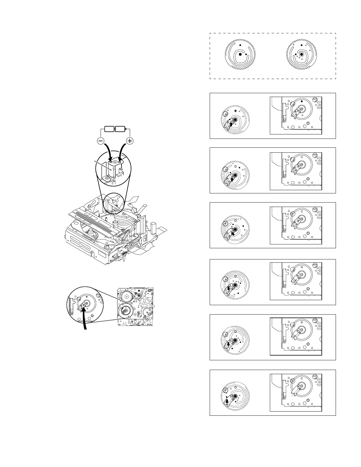
However, when the mechanism is removed from the main body,
it is set in the STOP mode. Therefore, after the mechanism is
removed from the main body, supply 3 V DC to the electrode
on the top of the loading motor to enter the mechanism mode
into the EJECT mode compulsory.
<Mechanism assembly/Cassette housing assembly>
<Back side of the mechanism assembly>
Fig. 2-2-1
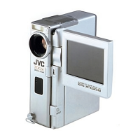
2.2.2 Explanation of mechanism mode
The mechanism mode of this model is classified into six
modes as shown in Table 2-2-1. Each mechanism mode can
be distinguished from others by the relative position of “Q”
mark on the sub cam gear to the inner or outer protrusion
on the main deck.
Refer to Fig. 2-2-2 to 2-2-7 below.
The EJECT mode, C IN mode and SHORT FF mode should
be recognized by the relative position of the “Q” mark to
the inner protrusion, while the STOP mode, REV mode and
PLAY mode should be recognized by that to the outer pro-
trusion.
<SUB CAM GEAR>
TOP VIEW BOTTOM VIEW
<C IN mode>
<EJECT mode>
<STOP mode>
<SHORT FF mode>
<PLAY mode>
<REV mode>
Fig. 2-2-2
Fig. 2-2-3
Fig. 2-2-4
Fig. 2-2-5
Fig. 2-2-6
Fig. 2-2-7