HX-Z1
21
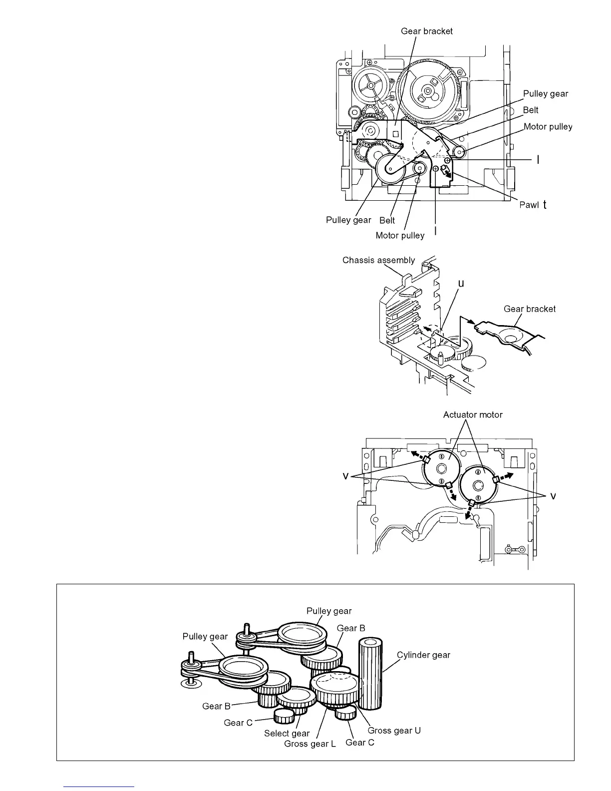
3.1.8 Removing the actuator motor and belt
(See Fig.18~21)
(1) Remove the two screws I retaining the gear bracket
(See Fig.18).
(2) While pressing the pawl t fixing the gear bracket in the ar-
row direction, remove the gear bracket
(See Fig.18).
(3) From the notch u section on the chassis assembly fixing
the edge of gear bracket, remove and take out the gear
bracket(See Fig. 19).
(4) Remove the belts respectively from the right and left actu-
ator motor pulleys and pulley gears(See Fig. 18).
(5) After turning over the chassis assembly, remove the actu-
ator motor while spreading the four pawls v fixing the right
and left actuator motors in the arrow direction(See Fig.
20).
[Note]
When the chassis assembly is turned over under the condi-
tions wherein the gear bracket and belt have been removed,
then the pulley gear as well as the gear, etc. constituting the
gear unit can possibly be separated to pieces. In such a case,
assemble these parts by referring to the assembly and config-
uration diagram in Fig. 21.
Fig.18
Fig.19
Fig.20
Assembly and Configuration Diagram
Fig.21
 Loading...