11 Safe-Drive™
155
11.5.1 Sensor inseron
•
•
1
1 Insert the sensor to the Inner casing. Make sure that
the sensor cable gland has been taken off and that the
latch on the Inner casing is unlocked. Match the
bayonet closing with sensor flange so that the latch is
slightly to the le of top and sensor cable passage is
straight down.
2 When sensor flange is flush with the boom of the
Inner casing, turn Inner casing 60 degrees (1/6 turn)
clockwise to lock it to the flange.
3 Push down the locking latch to secure the
connecon.
2
1 Put the Inner casing with sensor on a table or similar
raised surface so that the hand wheel has space to turn.
Fit the Outer casing over the Inner casing. To match
the casings, check that the groove on the Inner casing
matches the groove on the Outer casing. The latch of
the Inner casing should be slightly to the right from top
and the handle of the Outer casing should point up.
2 Turn the hand-wheel clockwise unl it stops to draw
the sensor into the Retractor. The sensor should now
be inside the Retractor and about 14 cm (5 1/2’’) of the
screw thread should sck out of the middle of the
wheel.
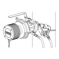
3 Take a firm hold of the hand-wheel and the handle
and li the Retractor (with sensor) over the isolaon
valve flange. Keep handle up and make sure that the
latch on the Outer casing is open.
4 1 Turn the Retractor 60 degrees clockwise (i.e. to the
right) to lock the bayonet.
2 Push down the latch on the Outer casing to secure
the connecon.
3 Insert safety pin.
 Loading...