Do you have a question about the K-Patents PR-23-GP and is the answer not in the manual?
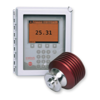
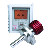
Overview of different PR-23 sensor models and their applications.
Explains how the refractometer measures liquid concentration using light refraction.
Essential safety precautions for handling and operating the refractometer system.
Information regarding K-Patents product warranty terms and conditions.
Guidelines for the proper disposal of obsolete equipment.
Detailed breakdown of the PR-23 inline refractometer sensor's components and structure.
Guidelines and considerations for optimal sensor placement and installation.
Overview of the DTR's features, display, and keyboard functions.
Instructions for installing the DTR enclosure in indoor environments.
Details on wiring the sensor to the transmitter and power supply connections.
Discusses causes of prism coating and methods to prevent it.
Information on available wash media (steam, water) and configuration.
Step-by-step guide for initial system startup and checks.
Performing preliminary checks before powering up the system.
Verifying system calibration against laboratory results.
Procedures for testing the functionality of the prism wash system.
How to navigate menus, use keyboard functions, and configure display settings.
Explains the purpose and usage of each key on the DTR keyboard.
Customizing display format, backlight, contrast, and language settings.
Accessing system details, calibration data, and network configuration.
Monitoring sensor performance through optical images and diagnostic values.
Analyzing the sensor's optical image for diagnostic purposes.
Understanding optical images when using the Image Detection Stabilization (IDS) algorithm.
Interpreting various diagnostic values displayed by the sensor.
Procedures for verifying sensor calibration and ensuring accuracy.
Adjusting signal damping for noise reduction and process stability.
Standard damping for slow processes, set via damping time parameter.
Fast damping for step changes, providing shorter settling times.
Limiting the maximum rate of change for the output signal.
Setting up system hold functions for wash cycles or external signals.
Using an external switch to temporarily hold the measurement result.
Automatically holding the output signal during prism wash cycles.
Setting a time window to ignore short measurement interruptions.
Preventing measurement when image quality is below a set limit.
How different hold functions interact with each other.
How signal filtering is affected when the measurement is in hold.
Specific considerations for using hold functions with the DD-23 system.
Assigning functions to relays, switches, and configuring mA outputs.
Configuring the two built-in relays for sensor output or alarms.
Configuring the four switch inputs for various functions like HOLD or WASH STOP.
Setting the zero and span values for the 4-20 mA output signals.
Detailed steps for chemical curve setup and field calibration.
Defines the theoretical concentration curve based on nD and TEMP.
Setting display units for concentration and temperature, and number of decimals.
Adapting calibration to factory laboratory determinations using process data.
Procedures for entering field calibration parameters supplied by K-Patents.
Adjusting the concentration measurement by changing the f00 bias parameter.
Setting parameters for automatic prism wash cycles.
Describes the automatic prism wash cycle phases: precondition, wash, and recovery.
Configuring wash time, interval, temperature limits, and wash check settings.
Monitoring humidity and replacing the dryer when necessary.
Procedures for inspecting and replacing prism components.
Step-by-step guide for safely taking apart and reassembling the sensor.
Identifying and resolving hardware-related issues using diagnostic LEDs.
Troubleshooting steps for a blank display issue.
Explains the function and status of diagnostic LEDs for troubleshooting.
Steps to reset display settings if the screen is unreadable.
Diagnosing and resolving the "NO SENSOR" message.
Diagnosing and resolving the "NO SIGNAL" message.
Troubleshooting "SHORT-CIRCUIT" messages related to sensor cables.
Addressing issues related to high sensor humidity.
Troubleshooting high sensor temperature conditions.
Addressing high transmitter temperature warnings.
Diagnosing and resolving low transmitter voltage issues.
Troubleshooting issues with relays and input switches.
Diagnosing errors related to the output signal during normal operation.
Troubleshooting common measurement errors and messages.
Resolving measurement issues caused by excessive external light.
Diagnosing causes for the "NO OPTICAL IMAGE" message.
Troubleshooting prism coating issues and performing manual cleaning.
Addressing light interference reaching the prism.
Resolving issues related to low optical image quality, often due to scaling.
Understanding and resolving the "NO SAMPLE" condition.
Diagnosing and resolving temperature measurement faults.
Identifying causes for concentration drift during normal operation.
Diagnosing issues related to the prism wash system and associated messages.
Understanding the "EXTERNAL HOLD" message.
Interpreting messages related to prism wash cycle phases.
Addressing warnings indicating insufficient wash effectiveness.
Troubleshooting prism wash failures.
Understanding and resolving "EXTERNAL WASH STOP" conditions.
Diagnosing low temperature wash stop conditions.
Understanding "NO SAMPLE/WASH STOP" messages.
A comprehensive table listing diagnostic messages and their causes.
Information on electrical and mechanical compatibility between sensors and transmitters.
Defines the refractive index and Brix measurement ranges for PR-23 sensors.
Detailed specifications, model codes, and mounting for the PR-23-AC.
Explains the model code structure for the PR-23-AC sensor.
Defines the model code for PR-23-AC mounting hardware.
Key technical specifications for the PR-23-AC sensor.
A detailed list of parts for the PR-23-AC sensor assembly.
Specifics on mounting the PR-23-AC sensor in process pipes.
Details on using I-Line fittings for PR-23-AC installation.
Information regarding 3-A Sanitary Standard compliance for PR-23-AC.
Specifications, model codes, and mounting for the PR-23-AP probe sensor.
Explains the model code structure for the PR-23-AP sensor.
Defines the model code for PR-23-AP mounting hardware.
Key technical specifications for the PR-23-AP sensor.
A detailed list of parts for the PR-23-AP sensor assembly.
Specifics on mounting the PR-23-AP probe sensor in tanks and walls.
Details on using I-Line fittings for PR-23-AP installation.
Information regarding 3-A Sanitary Standard compliance for PR-23-AP.
Specifications, model codes, and mounting for the PR-23-GC.
Explains the model code structure for the PR-23-GC sensor.
Key technical specifications for the PR-23-GC sensor.
A detailed list of parts for the PR-23-GC sensor assembly.
Specifics on mounting the PR-23-GC sensor in pipe elbows and straight pipes.
Specifications, model codes, and mounting for the PR-23-GP.
Explains the model code structure for the PR-23-GP sensor.
Key technical specifications for the PR-23-GP sensor.
A detailed list of parts for the PR-23-GP sensor assembly.
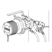
Specifics on mounting the PR-23-GP sensor using flowcells.
Specifications, model codes, and mounting for the PR-23-RP refinery model.
Explains the model code structure for the PR-23-RP sensor.
Key technical specifications for the PR-23-RP sensor.
A detailed list of parts for the PR-23-RP sensor assembly.
A list of parts specific to the PR-23-RP sensor head.
Provides dimensional drawings for the PR-23-RP sensor.
Specifics on mounting the PR-23-RP sensor in process lines and flowcells.
Details on the prism wash system for the PR-23-RP, including components.
Specifications, model codes, and mounting for the PR-23-M/MS Teflon body sensor.
Explains the model code structure for the PR-23-M sensor.
Key technical specifications for the PR-23-M sensor.
A detailed list of parts for the PR-23-M sensor assembly.
Explains the model code structure for the PR-23-MS sensor.
Key technical specifications for the PR-23-MS sensor.
A detailed list of parts for the PR-23-MS sensor assembly.
Specifics on mounting the PR-23-M/MS sensor using G1/2" or 1/2" NPT connections.
Specifications, model codes, and mounting for the PR-23-W Saunders body sensor.
Explains the model code structure for the PR-23-W sensor.
Key technical specifications for the PR-23-W sensor.
A detailed list of parts for the PR-23-W sensor assembly.
Specifics on mounting the PR-23-W sensor with Saunders valve body.
Details on ATEX, FM, and CSA approved models for explosive environments.
Lists the components of the PR-23 system for potentially explosive atmospheres.
Installation guidelines for PR-23 systems in potentially explosive atmospheres.
Specifications and mounting for intrinsically safe sensors in hazardous locations.
Components of the intrinsically safe PR-23 system including sensor and transmitter.
Guidelines for mounting intrinsically safe sensors, isolators, and transmitters.
Explains compatibility between DTR/STR transmitters and PR-23 sensors.
Details on DTR program versions and their new features.
Breakdown and explanation of the DTR and interconnecting cable model codes.
Explains the model code structure for the DTR and STR transmitters.
Defines the model code for interconnecting cables.
Technical specifications for the DTR transmitter and interconnecting cables.
Detailed technical specifications for the DTR indicating transmitter.
Technical specifications for the interconnecting cables.
List of parts for the DTR and STR indicating transmitters.
Overview of the Safe-Drive™ system components and functionality.
Technical specifications for the Safe-Drive™ sensor, isolation valve, and retractor.
Lists of parts for the PR-23-SD sensor and the SDI2 isolation valve.
Detailed list of parts for the PR-23-SD sensor.
Detailed list of parts for the Safe-Drive™ isolation valve.
List of parts for the Safe-Drive™ retractor tool.
Detailed instructions for mounting the Safe-Drive™ system components.
Steps for welding the Safe-Drive™ isolation valve to a process pipe.
Procedures for safely inserting and removing the sensor using the Retractor tool.
Step-by-step guide for inserting the sensor using the Safe-Drive™ Retractor.
Step-by-step guide for removing the sensor using the Safe-Drive™ Retractor.
Steps for installing and removing wash nozzles for the Safe-Drive™ system.
Procedure for inserting the wash nozzle into the isolation valve.
Procedure for removing the wash nozzle from the isolation valve.
How to secure unused Safe-Drive™ connections with blind plugs.
Details on using Ethernet cables for DTR to PC or LAN connections.
Specifies standard Ethernet cable types and maximum length.
Steps for physically connecting the Ethernet cable to the DTR.
Configuring IP settings for the DTR and standalone computers.
Setting the IP address for the DTR for Ethernet communication.
Configuring IP settings on a standalone computer for DTR connection.
Steps to test the Ethernet connection using ping and diagnostic LEDs.
Accessing and using the DTR's built-in web interface for instrument control.
Using the virtual remote panel via a web browser for instrument control.
How to view and print the sensor verification results and certificate.
Protocols and formats for data acquisition from the DTR over Ethernet.
Details the UDP/IP protocol and request/response formats for data transfer.
Lists query messages (request-response pairs) for data collection.
Details error message keys and codes for troubleshooting Ethernet communication.
Procedures and requirements for verifying the sensor's refractive index.
Step-by-step guide for performing sensor verification using standard liquids.
How to view and print the sensor verification results and certificate.
Steps to take if the sensor verification fails.
Statement confirming compliance with EU/EEA requirements.
Confirmation of compliance with European ATEX directives.
Confirmation of compliance with European ATEX directives for intrinsically safe models.
| Type | Refractometer |
|---|---|
| Model | PR-23-GP |
| Light Source | LED |
| Power Supply | 24 VDC |
| Protection Class | IP67 |
| Measurement Range | 0-100 Brix |
| Accuracy | ±0.1% Brix |
| Resolution | 0.00001 nD |
| Process Temperature Range | -20°C to 130 °C |
| Ambient Temperature | -20 °C to +60 °C (-4 °F to +140 °F) |
| Pressure Rating | Up to 100 bar (1450 psi) |
| Process Connection | Variety of flange options |
| Wetted Materials | Stainless Steel 316L, Sapphire |
| Output Signal | 4-20 mA, HART |
| Certification | ATEX, IECEx |