805.79
K-Commander Loss-in-Weight Programming
Rev: G Produced by the K-Tron Institute
LWF Page 10: Overview Screen, Continued
Page 10
graphic
description
The following is a listing and description of each variable on this page.
A "` " mark shows the values that you can edit. A "#" indicates that the
value is changed by a Function key. A $ symbol indicates that the value
can be changed but you should let the controller do it for you.
Display Element Description
130.67
130.67
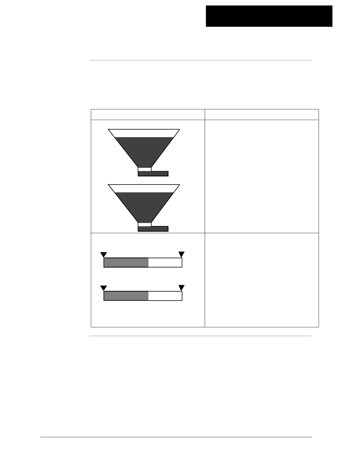
This graphic shows the feeder
running and the hopper emptying
as the feeder is running. The very
top of the hopper represents the
Scale Range. When the feeder is
running the lower long tube turns
green and when an alarm occurs,
this section turns red. When you
acknowledge an alarm, the tube
turns yellow. The value of net
weight is displayed next to this
icon.
DRIVE COMMAND
57.77
DRIVE COMMAND
57.77
This graphic shows drive
command. The point to the left is
the Min Drive Command Limit and
the point to the right is the Max
Drive Command Limit. If the drive
command exceeds 100%, the active
portion will extend to the right
beyond the bar outline. The alarm
points are in red. The actual value
of drive command is shown above
the bar.
Continued on next page