Page 13
INSTALLATION GUIDE - REMOTE ACCESS CONTROLLER RAC 4XT • PK3191_10_14
manufacturer.
CAUTION:
Refer to the wiring label on the access
door, the wiring diagram & tables in Annex
A, or the detailed peripherals connections
in Annex B.
IMPORTANT:
Every wire must pass through a strain
relief as connected in step 4.
Follow the indications below for the
different peripherals being connected.
The actual items to connect will vary based
on the system configuration ordered.
NOTE: Refer to detailed wiring diagrams
provided in Annex B.
1. Electric strike or electromagnetic lock
(locking device)
Refer to Annex B, Figure 4,5,6 & 7 for
detailed wiring.
IMPORTANT:
Kaba Ilco does not provide technical or
field support for 3rd party locking devices.
Please consult the device manufacturer
for support.
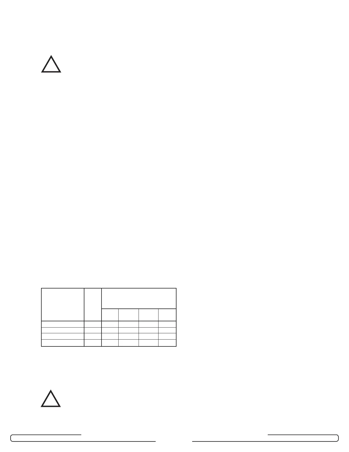
The following table indicates the maximum
recommended wire lengths that can be
used for typical locking devices, based on
wire gauge.
NOTE: The Maximum Recommended Wire
Length is the approximate wire length
that causes a 5% voltage loss in the
wire, using a 12-volt locking device at
the rated current included.
CAUTION:
This table is for reference only. Actual
wiring requirements for specific devices
may differ. Always follow the locking device
manufacturer’s wiring recommendations
as well as local building codes.
1.1 Install and route a 2-conductor cable from
the controller PCB to the desired location
of the electric strike or electromagnetic
lock.
1.2 If installing an electric strike, install the
diode across the terminals of the locking
device, using the crimp connectors
provided in the hardware bag if needed.
IMPORTANT:
Do not reverse the diode polarity as
indicated on the wiring diagram.
CAUTION:
To prevent a possible short, the diode
must not be in contact with electric strike.
If required cut the diode ends shorter.
1.3 Mount the locking device in the
desired location and connect as
per manufacturer’s instructions. For
connections between locking device and
controller PCB refer to Annex A, Table 3.
2. Request to Exit button (REX)
Refer to Annex B, Figure 8 for detailed
wiring.
Mount the device at the desired location
and run a 2-conductor cable from the
request to exit button to controller PCB
connector J8, pins 3 & 4. Connect as per
Annex A, Table 3.
3. Remote Unlock button
Refer to Annex B, Figure 8 for detailed
wiring.
Mount the device at the desired location
and run a 2-conductor cable from the
remote unlock button to the controller
PCB connector J8, pins 1 & 2. Connect as
per Annex A, Table 3.
4. Motion Detector
Refer to Annex B, Figure 9 for detailed
wiring.
Mount the device at the desired location
and run a 4-conductor cable from the
motion detector relay’s terminal block to
controller PCB connector J8, pins 3 & 4.
Locking Typical Maximum Recommended
Device Type Current Wire Length,
(A) One-Way (feet)
AWG AWG AWG AWG
18 16 14 12
Electromag. Lock 0.28 170 265 425 675
Electric Strike 0.45 105 165 265 420
Double Electro. Lock 0.56 90 145 230 365
Other Devices 0.75 65 100 160 250
!
!