Page 12
INSTALLATION GUIDE - REMOTE ACCESS CONTROLLER RAC 4XT • PK3191_10_14
NOTE: Do not use the actual drawing from
Annex E of this manual to mark the
hole locations as the drawing is not
to scale.
3. Based on the type of surface the reader
is being installed on; drill the holes in the
wall according to the diameters indicated
on the drilling template DT-512738.
Metal surface mounting: install the back
plate onto the wall with the metal screws
provided in the installation hardware bag.
Drywall surface mounting: tap the
wall inserts (provided in the installation
hardware bag) into the wall using a rubber
mallet. Install the back plate onto the wall
with the wood screws provided.
4. Hook the reader enclosure onto the top of
the back plate and click into place.
5. Tighten down the supplied set-screw (M3 x
0.5) on the bottom of the reader to secure
the reader cover.
6. Connect the card reader wire to the terminal
blocks of the controller PCB as per Annex
A, Table 1, or refer to Annex B, Figure 3.
NOTE: If required to differentiate between
ingress & egress, ensure that
the appropriate connector on the
controller PCB is used.
Model R71-4XX Insert card reader
installation
NOTE: The minimum depth required for
mounting of the insert card reader is
4.5”.
1. Ensure all tools are available as indicated in
manual PK3166-T, included with the insert
card reader.
2. Referencing the drilling template DT-512152
included with the reader, mark the location
of the holes to be drilled and the rectangular
cut-out to be made.
NOTE: Do not use the actual drawing from
Annex F of this manual to mark the
hole locations as the drawing is not
to scale.
3. Using the appropriate tools, cut out the
rectangular hole for the reader and drill
the screw holes as per drilling template
DT-512152 indications.
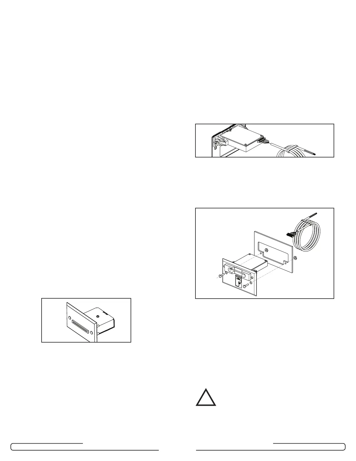
4. Attach the end of the wire with the
connector to the connector at the back of
the insert reader.
5. Mount the insert reader to the panel by
sliding the insert reader inside the cavity
and using the 2 spanner screws (6-32 x
3/4”) and the two hexagon lock nuts (6-
32), to screw the insert reader into the
panel.
6. Route the wire and connect to the RAC
4XT enclosure as per connections shown
in Annex A, Table 1, or refer to Annex B,
Figure 3.
NOTE: If required to differentiate between
ingress & egress, ensure that
the appropriate connector on the
controller PCB is used.
Step 7: Connect peripheral wiring
CAUTION:
Do not exceed the maximum cable length
indicated by the manufacturer of the
products being connected. In addition,
the wire used to connect the peripherals
to controller PCB must be of the proper
gauge and type as specified by the
Figure 16
Figure 17
Figure 15
!