Page 19
INSTALLATION GUIDE - REMOTE ACCESS CONTROLLER RAC 4XT • PK3191_10_14
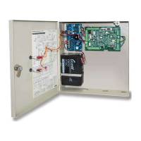
5.7 Power Failure
In the event of an electrical failure the RAC
4XT system will recover its configuration
automatically if power is restored within 3
days.
When electrical power is restored after a
power failure, verify the status of the LED D41
on the controller PCB. If the LED is OFF use an
initialization card with the reader and perform
a time reset on the RAC 4XT as per the FDU
or ATLAS manuals.
NOTE: When the power to the RAC 4XT is
too low (power failure, low voltage in
battery back-up) the controller PCB
stops functioning and the relays on
the controller PCB or the expansion
board will return to their normal state.
Any peripheral connected to the relays
will then be either in a normally open
(NO) or normally closed (NC) state,
dependent on the wiring.
5.8 Loading Recommendations
CAUTION:
Do not exceed the load limitations of the
RAC 4XT system.
The maximum recommended load for all
output relays in the RAC 4XT system is 1 Amp
at 30 VDC. The tamper switch rating is 1 Amp
at 30 VDC.
The current supplied by the controller PCB is
for the locking device used is 0.75 Amps from
connector J18, pin 1. Refer to Annex A, Table
3.
5.9 System Deactivation
In order to deactivate the RAC 4XT system,
disconnect both terminals from the battery
back-up (if equipped), then disconnect the
AC power either by removing the power
adaptor from the wall outlet, or by shutting
off the main power to the electrical outlet the
system is connected to.
!