Page 4
INSTALLATION GUIDE - REMOTE ACCESS CONTROLLER RAC 4XT • PK3191_10_14
2.2 Components
2.2.1 Controller box
(A) RAC 4XT Enclosure & Access Door:
holds the controller board (PCB),
power supply, relay expansion board
(optional), and battery back-up
(optional). Knockouts are available
on 3 sides for routing of peripheral
cables.
(B) Power Supply: provides the DC
power required for operation of the
controller PCB and all peripherals.
(C) Controller Board (PCB): controls all
the features of the RAC 4XT system.
(D) Tamper Switch: attached to the RAC
4XT enclosure to generate an alarm if
the box is opened during operation.
(E) Power & Battery Status LEDs:
provides visual indication of the
operational status of the RAC 4XT
system. Battery status LED is only
used on battery back-up equipped
systems.
(F) Cam-lock with Key: to provide secure
locking and to control access to the
RAC 4XT enclosure.
Optional components:
(G) Battery Back-up: 12 VDC battery
providing up to 4 hours of operation
in the event of a power failure.
(H) Relay Expansion Board: interface
board providing 8 relay outputs
that can be used to control relay-
equipped equipment. As example, it
can be used with an elevator to call
the elevator or to provide access only
to specific floors for certain guests or
staffs.
Not shown:
(I) Cables: cables required for
connections of the LEDs, power
supply and controller PCB. If
equipped, will also include cable for
connection of battery back-up and /
or relay expansion board.
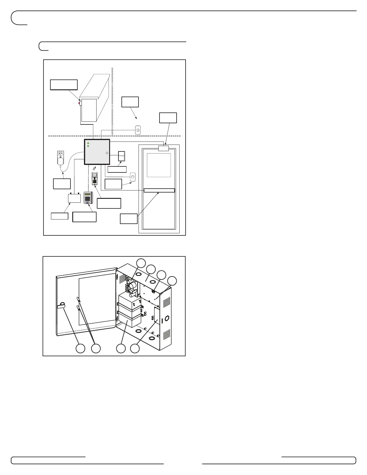
2.0 Product Description
Front Desk
Non-Secure Side
Secure Side
Remote Unlock
Fire Alarm
Ingress
Reader
Egress
Reader
Battery
12V
RAC 4XT
+
Power Status
PULL
FIRE
Battery Status
-
Request
to Exit
Power
Adaptor
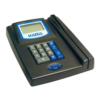
Programming
(M-Unit)
Programming
(FDU)
Locking
Device
Figure 2
B
A
D
C
HGEF
Figure 3