Page 10
INSTALLATION GUIDE - REMOTE ACCESS CONTROLLER RAC 4XT • PK3191_10_14
a hammer & screwdriver / awl, and from
the inner side of the enclosure tap out the
small metal disk.
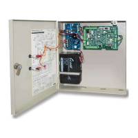
3. Based on the amount of wires to be
routed, attach the appropriate strain
relief to the enclosure as shown in
Figure 10. Do not attempt to route an
excessive amount of wires. If extra
strain reliefs are required please
contact Kaba Ilco.
4.2 Installation & Wiring Procedures
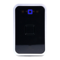
Step 5: Mounting the RAC 4XT enclo-
sure
Install the enclosure in the desired location
using the appropriate items from the hardware
bag.
NOTE: For easier access it is recommended
to remove the access door before
installation.
Step 6: Mounting and wiring card
reader(s)
For installation of the card reader(s) follow the
appropriate steps listed below, depending
on the type of card reader and configuration
being installed.
CAUTION:
Do not exceed the maximum cable length
indicated by the manufacturer of the
products being connected.
CAUTION:
Refer to the wiring label on the access
door, the wiring diagram & tables in Annex
A, or the detailed peripherals connections
in Annex B.
IMPORTANT:
Every wire must pass through a strain
relief as connected in step 4.
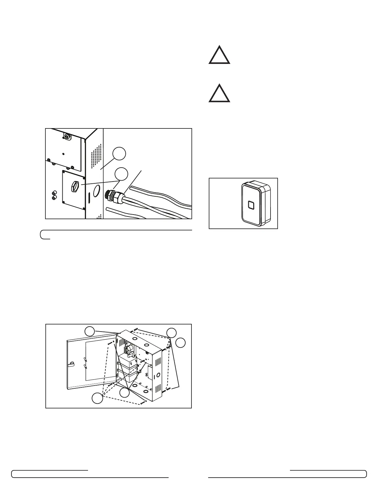
Model R79K-XXX Contactless card
reader installation
1. Remove the back plate and use it to mark
the holes for the cables and screws.
Alternatively, the drilling template DT-
514800 included with the reader can be
used.
NOTE: Do not use the actual drawing from
Annex H of this manual to mark the
hole locations as this drawing is not
to scale.
2. Drill the holes in the wall according to the
diameters indicated on the drilling template
in Annex H, based on the type of surface
the reader is being installed on.
Metal surface mounting: install the back
plate onto the wall with the metal screws
provided in the installation hardware bag.
Drywall surface mounting: tap the
wall inserts (provided in the installation
hardware bag) into the wall using a rubber
mallet. Install the back plate onto the wall
with the wood screws provided.
3. Connect the included cable to the terminal
block of the reader as shown in Annex A,
Table 1. Ensure that the correct wire color
is attached to the correct terminal block
connection.
Figure 10
A
V
Compression
Nut
A
U
T
S
X
Figure 11
OR
!
!
Figure 12