Page 14
INSTALLATION GUIDE - REMOTE ACCESS CONTROLLER RAC 4XT • PK3191_10_14
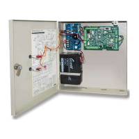
To power the motion detector, connect
the +12V input of the motion detector to
the red wire connecting the +DC OUT
terminal on the power supply and the 12V
input of the controller PCB (J16, pin 1),
as shown in Figure 8 of Annex B. Then
connect the GND input of the motion
detector to the black wire connecting the
-DC OUT terminal on the power supply
and the GND input on the controller PCB
(J16, pin 2). The use of wire connectors /
caps is recommended to ensure reliable
electrical connections.
NOTE: If the Egress reader is not used on
RAC 4XT, the motion detector can
also be powered from J14, pin 3 (12
V) and J14, pin 2 (GND).
5. Remote Programming Interface (RPI)
Refer to Annex B, Figure 10 for detailed
wiring.
Run a 4-conductor cable from the RPI to
terminal block J6 on the controller PCB.
Connect as per Annex A, Table 3.
6. Fire Alarm Panel
Refer to Annex B, Figure 11 for detailed
wiring.
Remove the jumper wire connected
between pins 3 and 4 of connector J18 on
the controller PCB and complete the fire
panel installation as per manufacturer’s
indications.
7. Tamper Switch to Premise Alarm
System
To wire the tamper switch to the premise
alarm system disconnect the wires on
controller PCB connector J7 pins 1 & 2,
and run a 2-connector cable from the
switch to the premise alarm system.
IMPORTANT:
The tamper alarm switch’s polarity is such
that when the door is closed the switch
itself is also in a closed state. Ensure that
the wiring to the premise alarm system is
done accordingly to prevent false alarms.
Step 8: Relay Expansion Board outputs
wiring
Refer to Annex B, Figure 12 for sample wiring
diagram.
The relay expansion board provides 8 relay
contacts for wiring & control of relay-enabled
peripherals, such as an elevator. The board
only provides normally open or normally
closed dry contacts, so no power is provided
by the board for peripherals.
When a relay expansion board is connected,
the controller PCB’s on-board single relay
output is disabled and any wiring of external
equipment must be done to the expansion
board.
As wiring of relay-controlled equipment may
vary between products please refer to the
product manufacturer’s instruction booklet
for proper instructions.
NOTE: Refer to Annex A, table 4 for specific
relay expansion board bypass
switches.
- If bypass switches are ‘ON’, the relays are
bypassed and the green LED associated
with that relay is turned OFF.
- If bypass switches are ‘OFF’ the controller
PCB can activate the relays. The
associated LEDs turn OFF during relay
activation.
NOTE: When the power to the RAC 4XT is
too low (power failure, low voltage in
battery back-up) the controller PCB
stops functioning and the relays on
the controller PCB or the expansion
board will return to their normal state.
Any peripheral connected to the relays
will then be either in a normally open
(NO) or normally closed (NC) state,
dependent on the wiring.
Elevator Controller Installation:
The most common application for a relay
expansion board is to control an elevator. As
the board contains 8 dry relay contacts, 8
common areas can be controlled. The relay
outputs are at the wiring input of each three
terminal connector (NO, COM, NC) on the
expansion PCB as well as being indicated on
the label on the inside of the door. Several
floors can be controlled by one relay (one
common area).