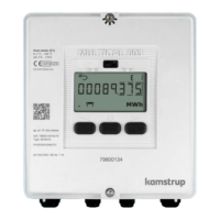
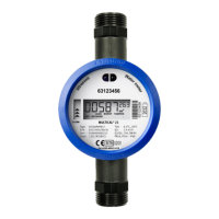
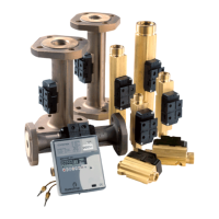
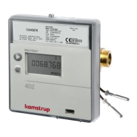
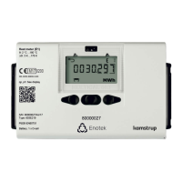
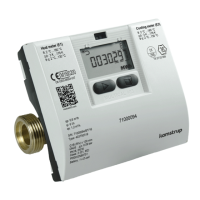
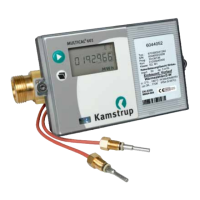
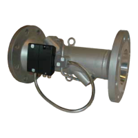
3.2.1 Accessories
30-26-857 Flow meter bracket
66-99-098 Data cable w/USB plug
66-99-099 Infrared optical reading head w/USB plug
66-99-102 Infrared optical reading head RS232 w/D-sub 9F
66-99-106 Data cable RS232, D-sub 9F
66-99-136 Infrared optical reading head for Kamstrup/EVL w/RS232 w/D-sub 9F
66-99-144 Infrared optical reading head for Kamstrup/EVL w/USB plug
66-99-370 Verification unit, Pt100 (to be used with METERTOOL)
66-99-371 Verification unit, Pt500 (to be used with METERTOOL)
66-99-619 Batteri backup (2xA cell lithium battery)
66-99-278 Short circuit pen (for total reset and total programming)
66-99-209 Short circuit jumper (for use with 2-wire temperature sensors)
16-40-080 Jumper for modules
65-56-4x-xxx Temperature sensor pair with connection head (2/4-wire)
59-20-177 Cable gland wrench 15 mm (hardened galvanised steel)
59-20-178 Cable gland wrench 19 mm (hardened galvanised steel)
66-99-103 Q144 dummy cover (144 mm x 144 mm) for blinding in panels/racks
66-99-634 24VAC High Power SMPS modul
66-99-622 230 VAC High Power SMPS modul
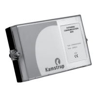
679xxxxxx2xx External Communication Box
66-99-724 METERTOOL for HCW
66-99-725 LogView for HCW
Contact Kamstrup A/S for questions about further accessories.
3.3 PROG, A-B-CCC-CCC
The Prog, which cannot be changed without breaking the verification seal, determines the meter’s legal parameters.
This means that the change must be made by an accredited laboratory.
The A-code states whether flow sensor (V1) is installed in inlet or outlet pipe. As the volume of water increases with
temperature, the calculator must correct for the installation form in question. Wrong programming or installation
results in measuring errors. Further details concerning installation of flow sensor in inlet and outlet in connection
with heat and cooling meters appear from section 5.1.
The B-code indicates the measuring unit used for the energy register. GJ, kWh or MWh are the most used units,
whereas only a few countries outside the EEA use Gcal.
The CCC-code states the calculator’s adaption to a specific flow sensor type to the effect that calculating speed and
display resolution are optimized for the selected flow sensor at the same time as type approval regulations about
minimum resolution and maximum register overflow are obeyed. We have divided the CCC-codes into smaller tables
in order to obtain a faster overview.
CCC(V1) states the CCC-code of the flow sensor connected to flow sensor input V1 on terminals 9-10-11 (or 10B-
11B). In most applications, this is the flow sensor used for energy calculation.
CCC(V2) states the CCC-code of a possible extra flow sensor, which can be connected on terminals 9-69-11 (or 69B-
79B). If V2 is not used, CCC(V2) is equal to CCC(V1). For leak surveillance CCC(V2) must be equal to CCC(V1).
 Loading...
