5
4. SYSTEM REQUIREMENTS
• An active network connection from a switch or router for control of compatible AV
over IP devices.
5. FEATURES
• Enables the management and configuration of multiple compatible SDVoE extenders
through a single WebGUI
• Provides control over the independent routing of video, audio and control signals
between all local compatible transmitters and receivers
• Control over matrix, video wall, and multiviewer modes using WebGUI macros
• WebGUI clearly displays the status of all connected Transmitters and Receivers,
including IP address, channel selection, etc.
• Can generate serial commands to directly control an external serial-controllable device
• Can be powered by Ethernet switches supporting the IEEE 802.3af 2003 PoE
standard (Optional)
• Trigger Control Keypad support for easy, single-button, macro activation (Optional)
• Standard control is available via WebGUI (remote or local), RS-232, Telnet, and IR Remote
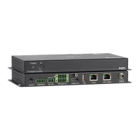
6. OPERATION CONTROLS AND FUNCTIONS
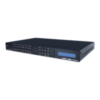
6.1 Front Panel
1. POWER LED: This LED will illuminate to indicate the unit is on and receiving power.
2. IR Window: Accepts IR signals from the included IR remote for control of this unit only.
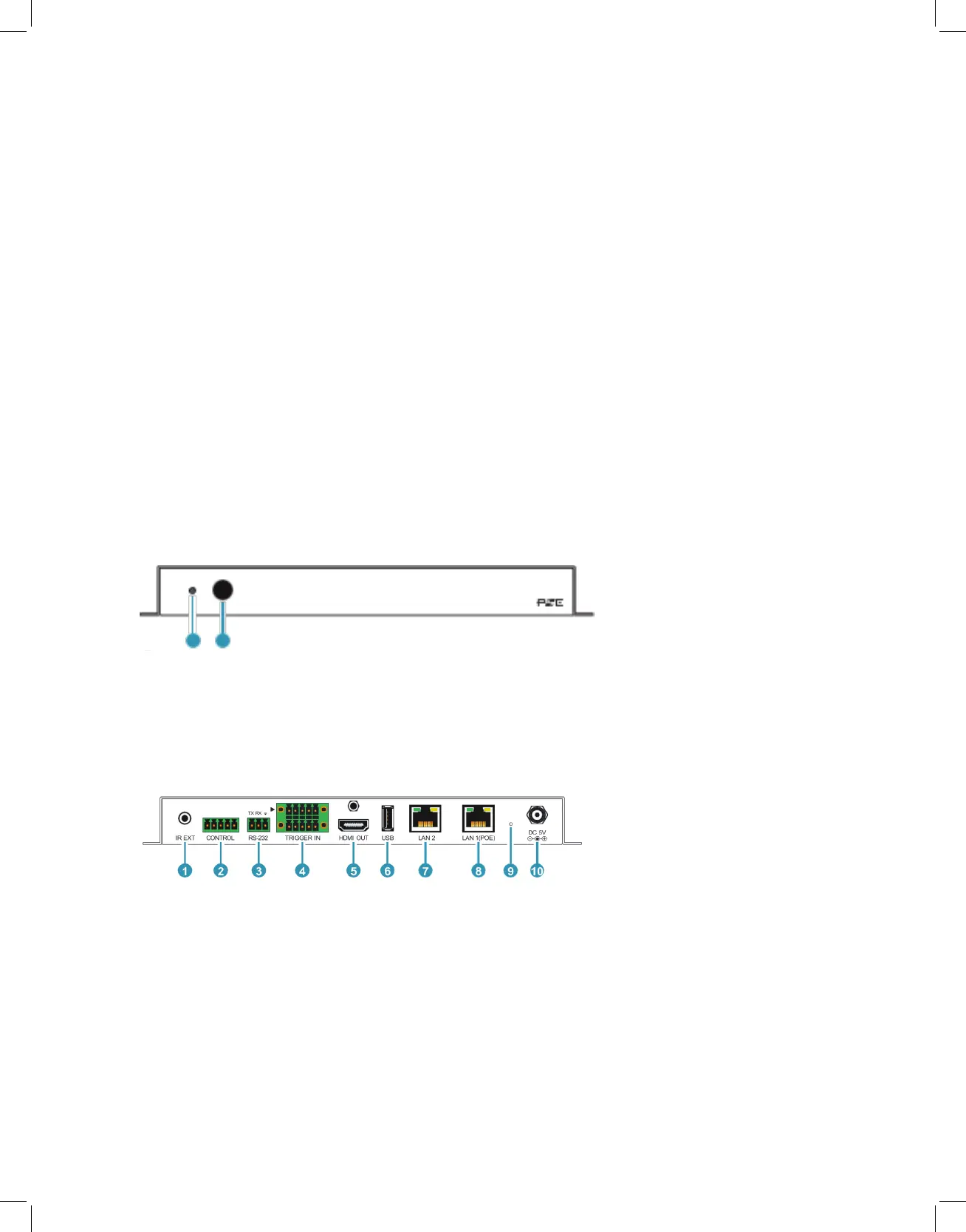
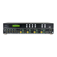
6.2 Rear Panel
1. IR EXT Port: Connect to the provided IR Extender to extend the IR control range
of the unit. Ensure that the remote being used is within direct line-of-sight of the IR
Extender.
2. CONTROL 5-pin Terminal Block: Connect to a serial controllable device for the
transmission of RS-232 signals.
3. RS-232 3-pin Terminal Block: Connect to a PC, laptop or other serial control device
with a 3-pin adapter cable to control the unit via RS-232.
4. TRIGGER IN 10-pin Terminal Block: Connect to the Trigger Control Keypad
POWER
1 2
IR