9
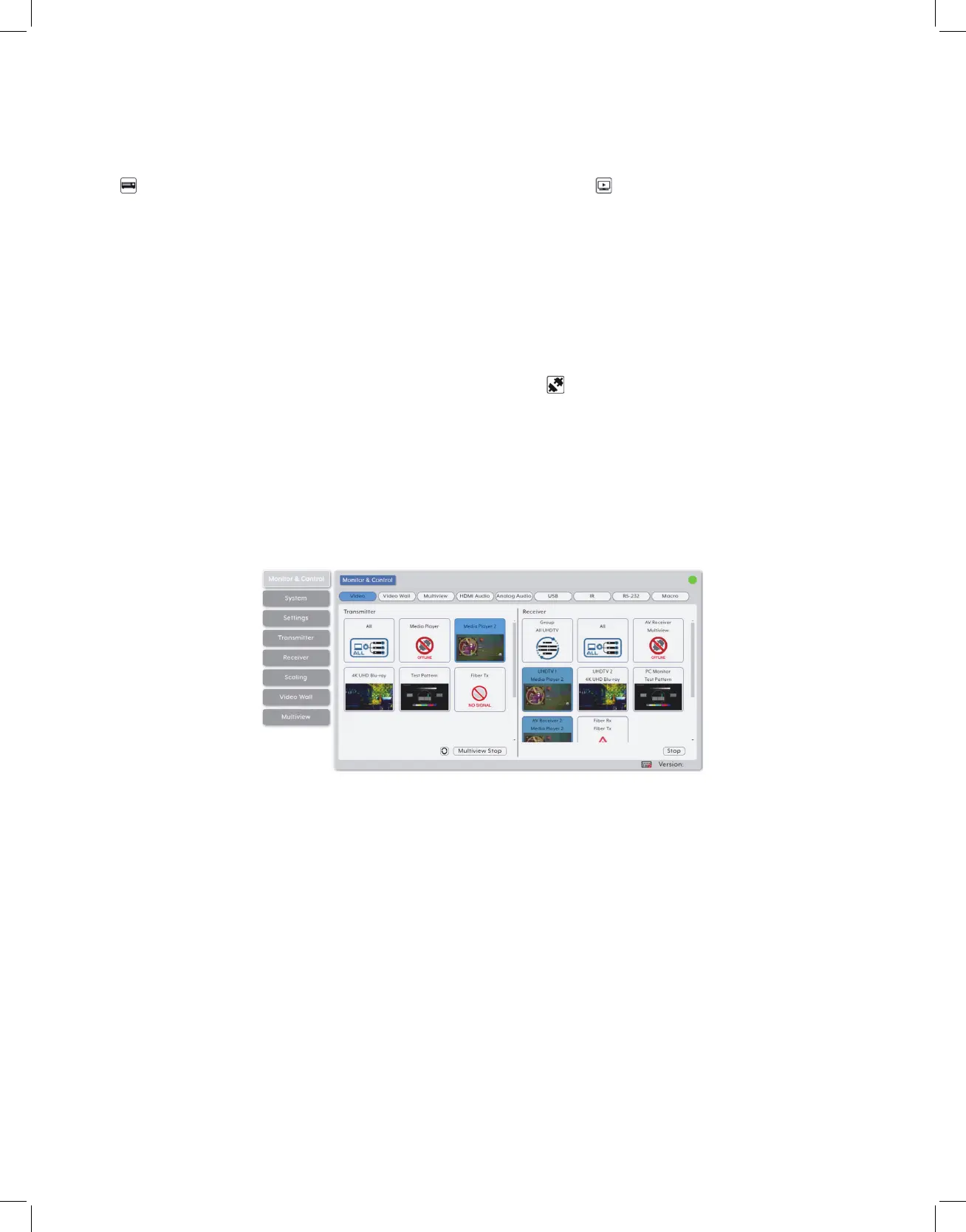
6.6.1 Monitor & Control Tab
This tab provides easy to use drag-and-drop control over all basic routing functionality
of the transmitters and receivers that have been detected within the local network. In all
sections, except for the Video section, transmitters are represented by the source icon
( ) and receivers are represented by the display icon ( ). Each of this tab’s sections
control the routing of a different type of interface that can be found on most compatible
transmitters, receivers or transceivers. These interfaces are: Video routing, Video Wall
routing, Multiview selection, HDMI Audio routing, Analog Audio routing, USB routing,
IR routing, RS-232 routing, and Macro activation. This tab’s controls are available even
when a user is not logged in, providing basic control over routing without exposing
system critical configuration areas.
Note: Units that were previously a part of the system, but are not currently detected will still be
displayed, however they will have a disconnected icon ( ) and cannot be used for routing.
1. Video Routing: Provides drag-and-drop control over the video routing between all
detected transmitters and receivers. Each transmitter and receiver box will display a
small, low framerate, video thumbnail to indicate what video is currently active.
Note: Certain operational modes (multiview, video wall) and some transmitters and receivers do
not support the video thumbnail feature.
• Video Transmitter: This section provides drag-and-drop buttons for all transmitters
detected by the system as well as a multi-option button target to stop video streams
from being transmitter.
Note: The IP Master Controller has an automatic bandwidth reduction feature to prevent situations
where a source’s streams will exceed 10Gbps, but in the unlikely event a transmitter’s streams
still require more bandwidth than is available, the video output may become visually unstable. In
these situations, it is recommended to reduce the resolution, framerate, or bit depth of the original
source.