INSTALLATION MANUAL OPERATION MANUAL INSPECTION LOG
KANNAD 406 AF-COMPACT
PAGE: 107
FEB 01/2008
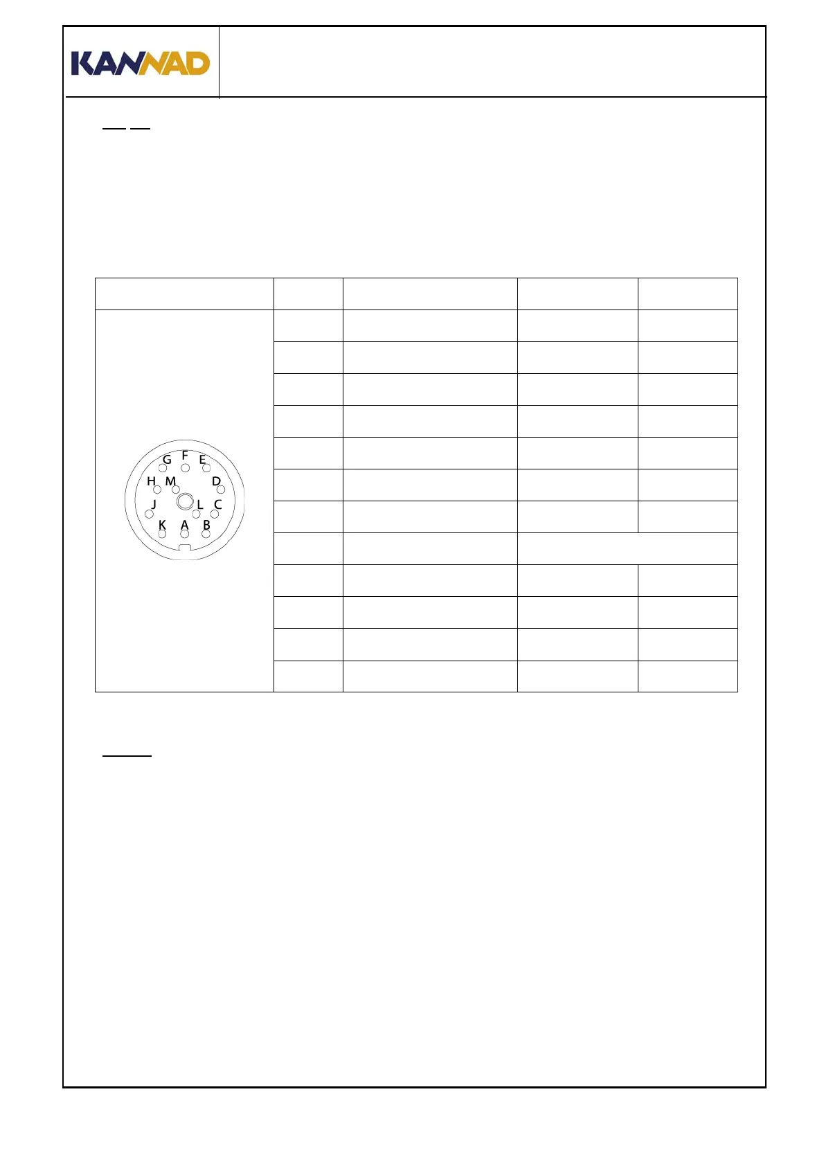
(a) J1
DIN 12 socket J1 is dedicated for connection to the Remote Control Panel,
to a Programming or Maintenance Dongles and/or to a programming
equipment (PR600).
IMPORTANT: Shielded cables are recommended. The required wires
are AWG24.
Table 1: J1 connector pin-out
(b)
J2
BNC female connector J2 is used to connect the outside antenna through a
50 Ω coaxial cable.
IMPORTANT: The length of the coaxial cable should not exceed 2 meters (6
ft) for a standard RG58 or equivalent coaxial cable. If the cable length
exceeds 2 meters, a low loss cable of attenuation less than 1 dB must be
used (See Important notice Section D. Outside antenna, page 6).
J1 PIN Signal Name Destination Direction
Viewed from
Front Face
J1-A RCP TEST/RESET RCP IN
J1-B DONGLE RX SMM / PGM IN
J1-C DONGLE CS SMM OUT
J1-D DONGLE SK SMM OUT
J1-E DONGLE TX SMM / PGM OUT
J1-F DONGLE ALE2P SMM OUT
J1-G RCP COMMON RCP OUT
J1-H RCP BUZZER Not used
J1-J RCP LED RCP OUT
J1-K N/C
J1-L DONGLE GND SMM / PGM OUT
J1-M N/C
 Loading...