INSTALLATION MANUAL OPERATION MANUAL INSPECTION LOG
KANNAD 406 AF-COMPACT
PAGE: 205
FEB 01/2008
B. Bracket installation procedure
• Determine the location of the ELT onboard according to paragraph A. ELT
and bracket installation recommendations page 204.
• The G-Switch axis shall be directed to sense the primary crash pulse along
the longitudinal axis of the aircraft. Reference to the G-Switch is given by
the arrow "Flight direction" on the label affixed to the top of the ELT.
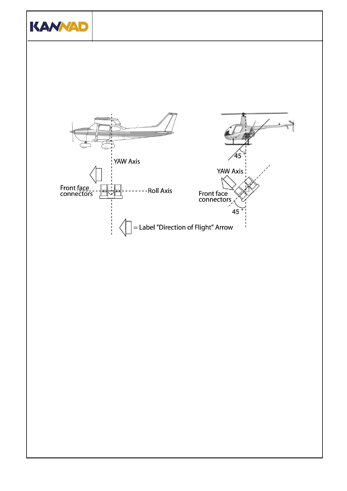
Figure 202: KANNAD 406 AF-COMPACT, axis of installation
(1) Fixed wing aircraft
The G-Switch sensor axis shall be pointed to sense the primary crash
pulse along the longitudinal axis of the aircraft (with maximum tolerance of
15°). Consequently, the KANNAD 406 AF-COMPACT shall be mounted
with the arrow of the "Flight direction" label pointed towards the front of the
aircraft.
(2) Helicopters
The standard version of the KANNAD 406 AF-COMPACT may be installed
on helicopter. The ELT unit should be mounted:
• with the front face connectors pointing downwards at a 45° angle to
the yaw axis;
• and with "Flight direction" arrow towards the front of the helicopter.
NOTE: Should the KANNAD 406 AF-COMPACT be installed onboard
helicopter, it will be necessary to make a special mounting base to install
the ELT.