V2.01
25359_EDEBDA0279-2320-1_EN
18
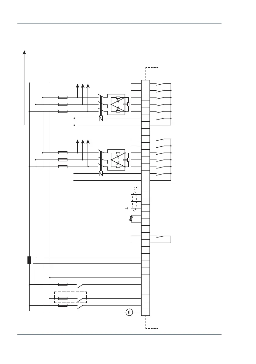
Installation and electrical connection of the system
PE
L1
EVU
Verbraucher / consumer
L2
L3
N
F1 F2 F3
1 2 10 11 20 21
L2 L3 k l
K L
30 31 70 71 90 91 92
A B
40 41 42 43 44 45 46 47 48 49 50 51 52 53
k1 k2 k3 k4 k5 k6 k7 k8 k9 k10 k11 k12
ϑ
Trenn-
vorrichtung/
circuit
breaker
weitere Stufen
further stages
Kompensationsanlage
power factor
correction equipment
Steuer-
spannung
driving voltage
100-240V
+/- 10%
50/60 Hz/
DC
Mess-
spannung
Measuring
voltage
30 ... 690V
Temperatur-
fühler
temperature
probe
Bus
Kontakt bei
Störung und
im Stromlosen
Zustand oen
contact is open
by no power
and alarm
*) HINWEIS: k6 bzw. k12 wahlweise Lüfteranschluss oder Kompensationsstufe
(Werkseinstellung = Lüfteranschluss)
(je nach Ausführung 6-stuger oder 12-stuger Regler)
*) NOTE: k6 or k12 optional fan connection or compensation stage
(factory default = fan connection)
(depending on version 6-stage or 12-stage controller)
Hinweis beachten!
Read information!
Messstrom / measuring current
Alarm
Steuerspannung / driving voltage <= 250 V
Steuerspannung / driving voltage <= 250 V
*)
*)
5.5 Measuring voltage connection Ph-N
 Loading...


