Q.2.60 March 2019
Page 3
© Copyright 2019 KE2 Therm Solutions, Inc., Washington, Missouri 63090
KE2 Compressor Sequencer OEM pn 21768
Quick Start Guide
Auxiliary Relay Board pn 21323
(When used with KE2 Compressor Sequencer OEM)
120/208/230 VAC
-40°F to 140°F (-40°C to 60°C)
-40°F to 140°F (-40°C to 60°C)
(2) temperature sensor / selectable inputs①
(1) pressure transducer
(1) selectable input
(1) 0 to 10 VDC / 0 to 5VDC- congurable for variable speed or
0V/10V for Digital Compressor Bypass Valve②③
(4) 5A FLA inducve
(1) 10A inducve external Digital Switch Relay - requires pn 21032
Fixed speed, variable speed, digital compressor, hot gas defrost relay,
master liquid line solenoid, unloader
Internal compressor temp, room temp, monitor temp, hot gas defrost
request, 2nd pressure, 2nd temp, compressor module alarm, high
pressure safety alarm, oil pressure safety alarm, system o.
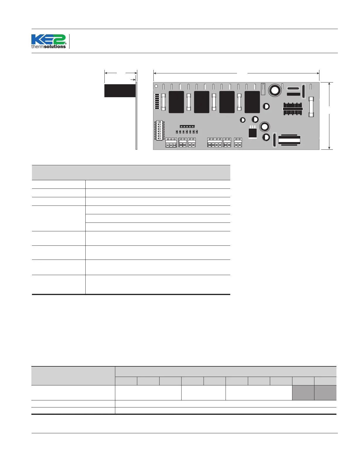
Dimensions & Specicaons
Auxiliary Relay Board
NO NC
COM
EARTH
11.20”
11.00”
5.70”
2.80”
3.25”
0.20”
0.20”
Ø0.150” Hole Thru
(6 places)
0.06”
1.60”
0.10”
ON
1 2 3 4
5 6 7 8
8.5”
3.25”
0.06”
1.50”
Applicaon:
The KE2 Compressor Sequencer OEM can be used on rack systems
with up to 8 stages of loading for a single suction group, or up to
10 stages of loading (5 per suction group) for dual suction groups.
For dual suction groups, the discharge line can be shared between
the two groups, or independent. The relays can also be used to con-
Type of Control
Total Number of Stages* (Compressor, Unloader)
1 2 3 4 5 6 7 8 9 10
KE2 Compressor Sequencer
OEM
+1 Aux Relay Board +2 Aux Relay Boards
KE2 Compressor Sequence OEM + 2 Aux Relay Boards (up to 5 stages per sucon group)
KE2 Compressor Sequence OEM + 2 Aux Relay Boards (up to 5 stages per sucon group)
*Relays can also be used as a master liquid line solenoid valve relay and/or hot gas bypass relay.
Please refer to the point to point wiring diagrams for each specic applicaon.
trol a Master Liquid Line Solenoid or act as a Hot Gas Defrost Relay.
When more stages of loading are required than available on the main
board, auxiliary relay boards can be added to increase the number
of available relays. Please refer to the chart below for the number of
required auxiliary boards for a specic application.
① Number of selectable inputs depends on
applicaon
② Digital Compressor Bypass Valve control
requires PN 21304
③
Controller is designed to operate with a
Copeland Scroll Digital Compressor.