SIN/COS at Channel 1
GB -7
2.4 Mechanical installation
All kind of works on the inverter may be carried out by authorized personnel in accordance
with the EMC and safety rules only.
• Switch inverter de-energized and await capacitor discharge time
• Pull off operator
• Remove plastic cover
• Removexingbolt
• Fix interface board beginning from the socket connector straightly
• Screwinxingbolt
• Attach plastic cover
3. Description of the Interface
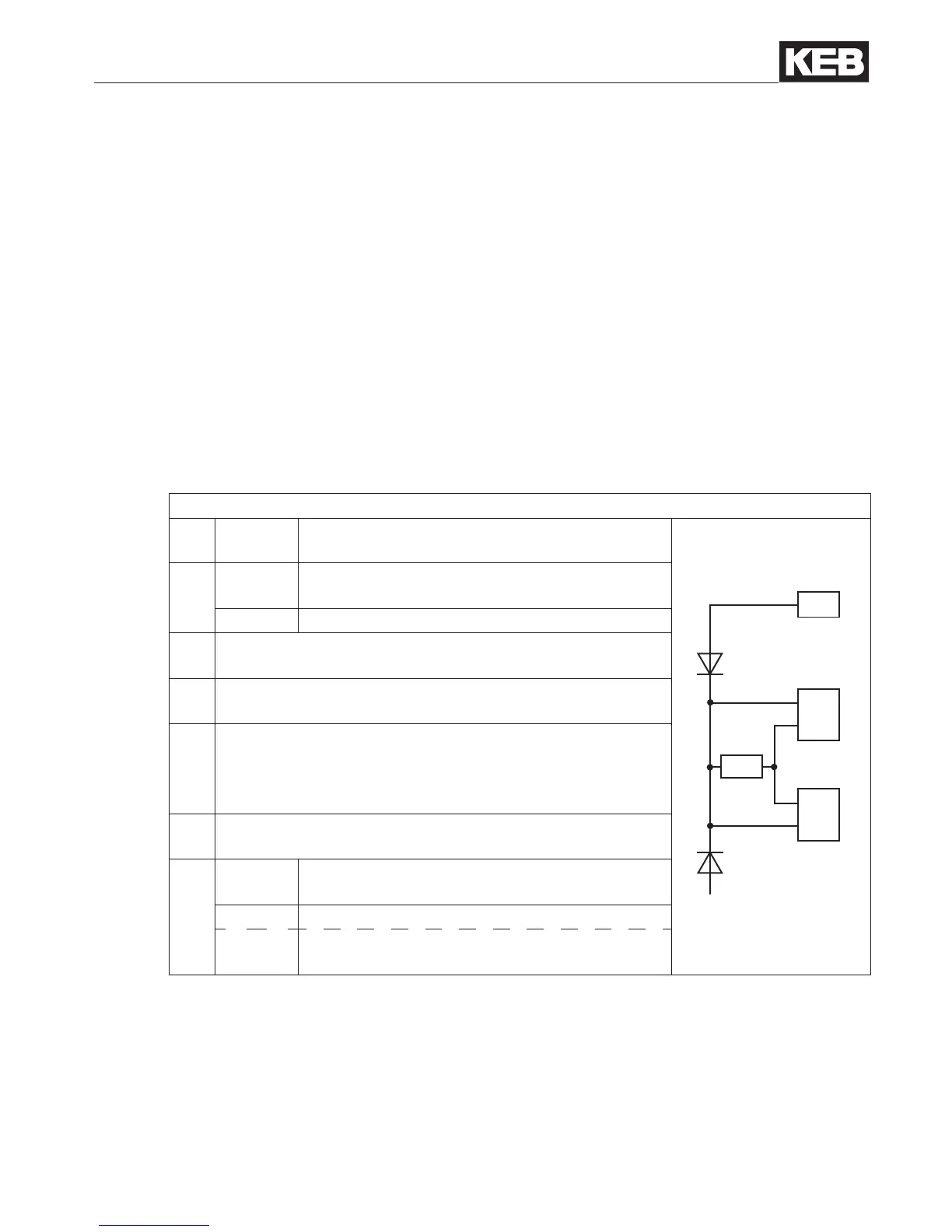
3.1 Voltage supply
Figure 3.1 Voltage supply of control and encoder interfaces
U
int 24 VDC Internal voltage supply of COMBIVERT.
X2A
X3A
X3B
5,2V
24V
5V
24V
5V
U
int
Uext
I
int
120 mA
at Hiperface, Sin/Cos, EnDat, SSI-Sin/Cos
and UVW.
170 mA at all other encoder interfaces.
U
ext
Control terminal strip (X2A) of the COMBIVERT with
external voltage supply 24…30 DCV.
24 V
Voltage output of encoder interfaces X3A and X3B for
encoder supply.
I
24V
Current I
int
reduces itself by draw current to the 5 V output
in accordance with the following formula:
5.2
V x I5V
I
24V
= Iint
- –––––––––
U
int
5 V
Voltage output for encoder supply. 5.2 V are obtained
from the 24 V voltage.
I
5V
300 mA
at Hiperface, Sin/Cos, EnDat, SSI-Sin/Cos
and UVW.
500 mA at all other encoder interfaces.
1 A
at external supply (dependent on the voltage
source)

 Loading...


