SIN/COS at Channel 1
GB -8
3.2 Channel 1
3.2.1 Specications
X3A Socket SUB-D15
Interface type SIN/COS
Inputs / tracks 1 Vss typical (0.6…1.2)
Limiting frequency 200 kHz
Increments per re-
volution
1…2048 inc (recommendation 1024 inc for speed upto 4500 rpm
Input resistance 120Ω
Max. line length
50 m, the value is additionally limited by the signal frequency, cable
capacity and supply voltage (see chapter „encoder line length").
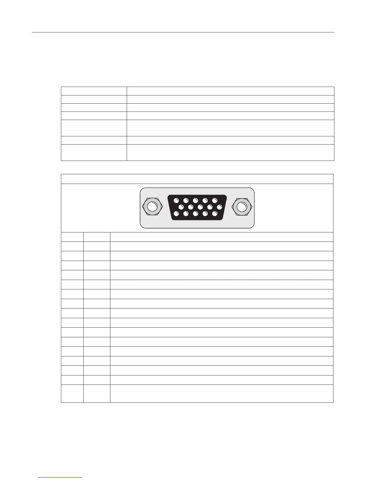
3.2.2 Description of X3A
Figure 3.2.2 Socket X3A
PIN Name Description
1 C- Signal input C- (difference signal to C+)
2 D- Signal input D- (difference signal to D+)
3 A- Signal input A- (difference signal to A+)
4 B- Signal input B- (difference signal to B+)
5 - -
6 C+
Absolute track for initial position and angular calculation
7 D+
Absolute track for initial position and angular calculation
8 A+ Incremental encoder input track A for counter and direction detection
9 B+ Incremental encoder input B for counter and direction detection
10 - -
11 24 V Power supply for encoder
12 +5.25 V Power supply for encoder
13 COM Reference potential for voltage supply
14 -R Signal input R- (difference signal to R+)
15 +R Zero track
– GND Connection for shield at the connector housing (is directly connected
with the inverter earth).
3.2.3 Input signals
Tracks C and D are giving an absolute signal to the control unit. The period is correspond
exactly to one mechanical revolution of the encoder. At starting the control unit will start
withthisrelativeinaccurateabsolutevalue.Withtherstzeropulsethepositionwillbecor-
rected. Thus approach to reference point is not necessary.

 Loading...


