102
Artikelnummer Größe I
N
I
a
U
N
ABCDEFGH
Part Number Size [A] [mA]
07.F0.T60-0009 07…09 (Chassis) 20 2,8 250V 161 38 71 152 151 59 59 5
07.R0.T60-0009 05…10 (Rack) 20 2,8 250V 182 45 85 173 172 73 66 5
09.F0.T60-1009 09…10 (Chassis) 8 30 3x440V 161 38 71 152 151 59 59 5
09.R0.T60-1009 09…10 (Rack) 8 30 3x500V 182 45 85 173 172 73 66 5
11.R0.T60-1009 11…13 (Rack) 20 67 3x500V 182 45 85 173 172 73 66 5
Technische Daten/Abmessungen Technical Data/Dimensions
200 V400 V
I
N
Nennstrom
I
a
max. Ableitstrom
U
N
Nennspannung
I
N
rated current
I
a
max. discharge current
U
N
rated voltage
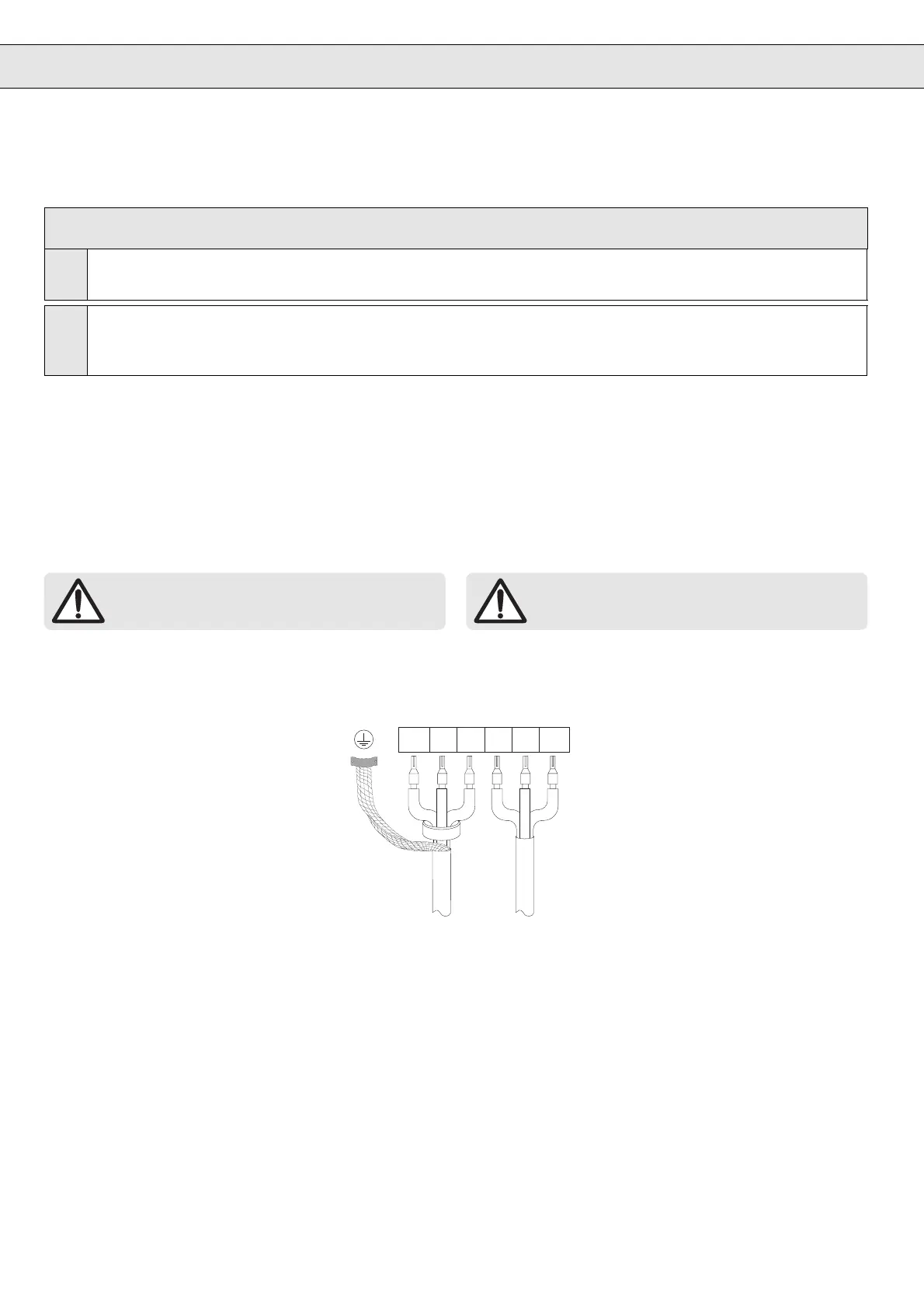
9.3.2 Korrekte Leitungsauswahl und -verlegung
Die Verwendung von abgeschirmten Steuer- und Motorkabeln
sowie das Verdrillen der Leitungen von Bremsoptionen verhindern
Störungen durch Abstrahlung der Leitungen.
Die Abschirmung der Kabel muß
beidseitig groß-
flächig
aufgelegt werden!
Als weitere Maßnahme empfiehlt es sich, an der Anschlußseite des
Frequenzumrichters einen Ferritring (Art.-Nr. 00.90.390-3201) um
das Motorkabel zu legen.
Ein Mindestabstand von 20 cm zwischen
Steuerkabel und Leistungskabeln verhin-
dert bei paralleler Verlegung eine
Störungseinkopplung.
Kreuzen sich Leistungs- und Steuerkabel,
so sollten sie in einem zueinanderliegenden
Winkel von 90° verlegt werden.
9.3.2 Correct Line Selection and Installation
The use of shielded control and motor cables as well as the twisting
of the lines of the braking options prevent the radiation from the
lines.
The shielding of the cables must be applied over a
large-area at both sides
!
As further measure we recommend to lay a ferrite ring (part no.
00.90.390-3201) around the motor cable at the connecting side of
the inverter.
A minimum distance of 20 cm between
control cable and power cable prevent a
interference coupling when the cables are
layed parallel.
In case power and control cable cross
each other they should be installed in an
angle of 90° to each other.
L1UL2L3VW
KEB Frequenzumrichter / KEB Inverter
Installation von KEB COMBIVERT und Filter im Stahlschrank
Um Störungen durch Abstrahlung des Frequenzumrichters und
damit eine Beeinflussung benachbarter Komponenten zu vermei-
den, KEB COMBIVERT und Filter in einen Stahlschrank installie-
ren.
Installation of KEB COMBIVERT and filter in steel cabinet
To prevent interferences through radiation from the frequency
inverter and thus an interference of adjacent devices install KEB
COMBIVERT and filter in a steel cabinet.
9.3.3 Konsequente Masseführung und gute Erdung
Beim Einbau von KEB COMBIVERT und Filter im Stahlschrank ist
auf eine großflächige Erdung zu achten (z.B. Montageplatte des
Schaltschranks). Entfernen von eventuell vorhandener Farbe zwi-
schen den Komponenten stellt eine flächige Kontaktierung sicher.
Die Erdung ist sternförmig, von einem zentralen Erdungspunkt aus,
an die entsprechenden Anschlüsse zu führen.
9.3.3 Consequent Earth Connection and good Earthing
Regarding the installation of KEB COMBIVERT and filter in a steel
cabinet use a large-area earthing (e.g. mounting plate of control
cabinet). Removing any existing paint between the components
ensures an area contacting. The earthing shall be done from point-
to-point starting at a central earthing point.
 Loading...


