23
ANTRIEBSTECHNIK
COMBIVERT F0
C.2 Drehrichtungssperre
Die Vorgabe der Drehrichtung kann mit dem Parameter C.2 einge-
schränkt werden.
C.2 Rotation Lock
The presetting of the rotational direction can be restricted by the
parameter C.2.
C.2 Funktion
F r keine Drehrichtung gesperrt
F - Drehrichtung rückwärts gesperrt
- r Drehrichtung vorwärts gesperrt
- - beide Drehrichtungen gesperrt
C.2 Function
F r none of the rotational directions locked
F - rotational direction reverse locked
- r rotational direction forward locked
- - both rotational directions locked
Wird eine gesperrte Drehrichtung angewählt, geht der Frequenz-
umrichter auf Low-Speed (LS).
5.5 Sollwertvorgabe
5.5.1 Analoge Sollwertvorgabe
Selecting a locked rotational direction causes the frequency inverter
to trip to Low Speed (LS).
5.5 Set Value Setting
5.5.1 Analog Set Value Setting
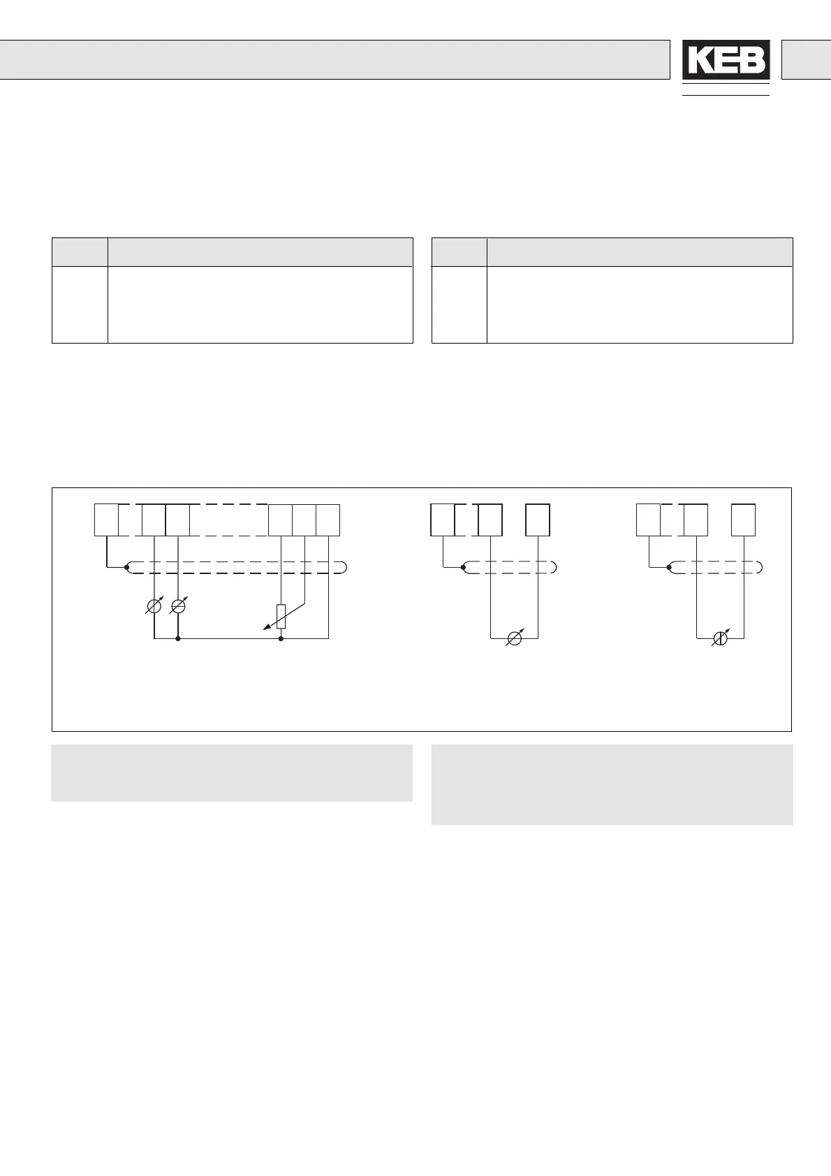
REF: set value input (terminal 17)
– Potentiometer 3…10 ký / 0,5 W
– Voltage signal 0…10 V DC, 0…±10 V DC
– Current signal 0…20 mA DC (solder jumper J1)
– Current signal 4…20 mA DC (solder jumper J1)
REF1: adding set value input (terminal 8)
– Voltage signal 0…±10 V DC
The voltage signal is added sign-correct to the set value
input REF.
REF2: 2nd set value input (terminal 9)
– Voltage signal 0…10 V DC
– Current signal 0…20 mA V DC, 4…20 mA V DC
The type of the input signal is determined with the parameter H.0
according to table 1.
REF: Sollwerteingang (Klemme 17)
– Potentiometer 3…10 ký / 0,5 W
– Spannungssignal 0…10 V DC, 0…±10 V DC
– Stromsignal 0…20 mA DC (Lötjumper J1)
– Stromsignal 4…20 mA DC (Lötjumper J1)
REF1: addierender Sollwerteingang (Klemme 8)
– Spannungssignal 0…±10 V DC
Das Spannungssignal wird vorzeichenrichtig zum Soll-
werteingang addiert.
REF2: 2. Sollwerteingang (Klemme 9)
– Spannungssignal 0…10 V DC
– Stromsignal 0…20 mA V DC, 4…20 mA V DC
Die Art des Eingangssignals wird mit dem Parameter H.0 gemäß
Tabelle 1 festgelegt.
Der KEB COMBIVERT F0 ist wie folgt voreingestellt:
Satz 0, 4, 5 und 6 Sollwertvorgabe analog durch o.13 = 3
Satz 1, 2 und 3 Sollwertvorgabe digital durch o.13 = 1
(Lötjumper J1 schließen)
(close solder jumper J1)
The KEB COMBIVERT F0 is preset as follows:
Set 0, 4, 5 and 6 presetting analog reference value through
o.13 = 3
Set 1, 2 and 3 presetting digital reference value through
o.13 = 1
489 16 17 18
3...10 kΩ,/0,5 W
417
+
18
0...±10 V DC
Ri = 56 kΩ
417
+
18
0...20 mA DC
4...20 mA DC
Ri = 500 Ω
+
+
0...±10 V DC
Ri = 56 kΩ
0É20 mADC, Ri = 250 Ω
4É20 mADC, Ri = 250 Ω
0É10 VDC, Ri = 4,4 kΩ

 Loading...


