11
ANTRIEBSTECHNIK
COMBIVERT F0
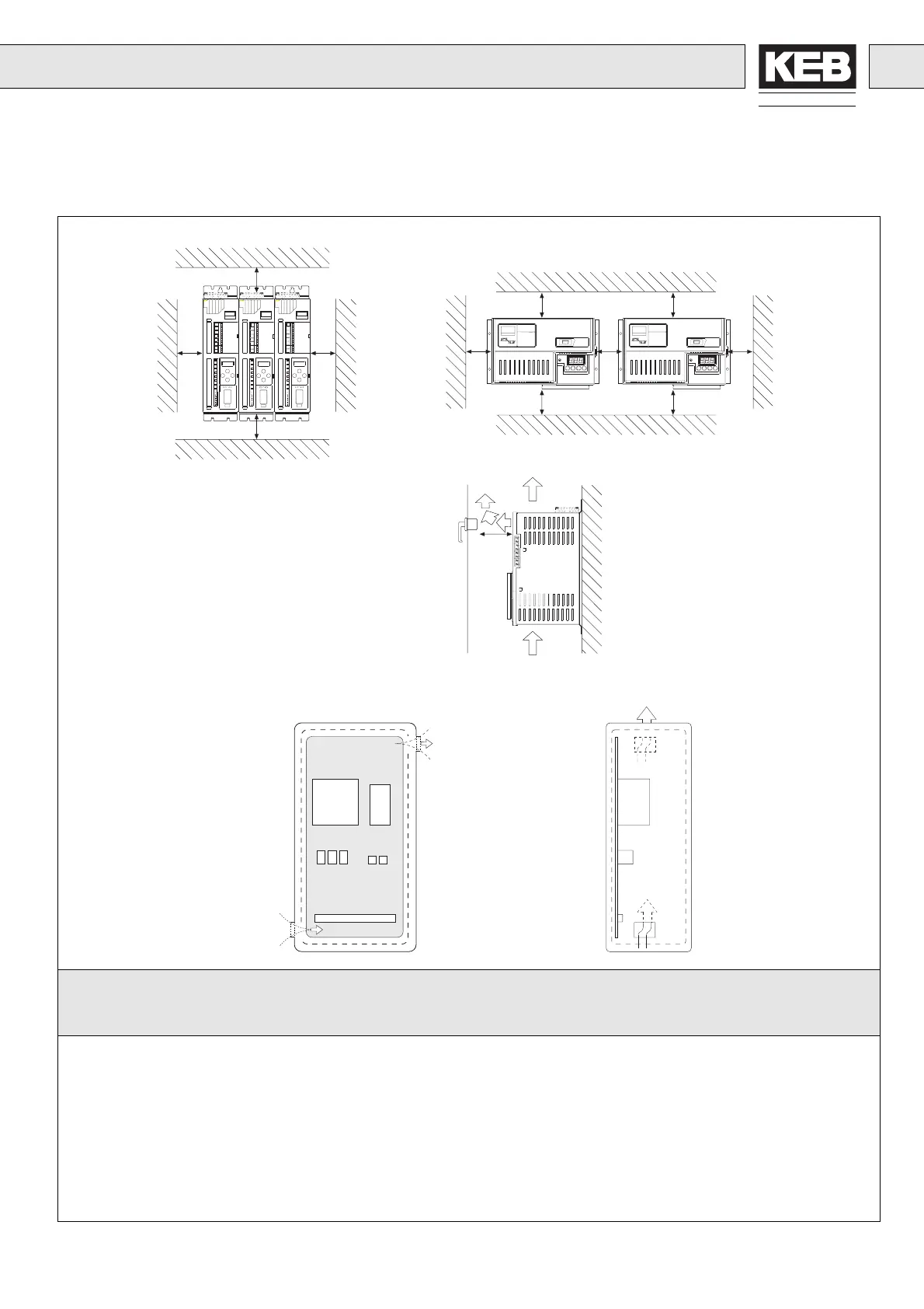
1.7.3 Control Cabinet Installation1.7.3 Schaltschrankeinbau
Verlustleistung (P
V
) bei Nennlast / Heat Dissipation (P
V
) at Nominal Load
Umrichtergröße P
V
bei 4 kHz P
V
bei 16 kHz
Inverter Size P
V
at 4 kHz P
V
at 16 kHz
05.F0 / 200 V 44 W –
07.F0 / 200 V 65 W 105 W
09.F0 / 200 V 70 W 135 W
10.F0 / 200 V 95 W 135 W
12.F0 / 200 V 110 W –
09.F0 / 400 V 65 W 140 W
10.F0 / 400 V 75 W 165 W
11.F0 / 400 V 110 W –
12.F0 / 400 V 130 W –
13.F0 / 400 V 165 W –
14.F0 / 400 V 215 W –
100
100
50
50
50
50
50
100
100
100
100
KEB
COMBIVERT
Kühllufteintritt
Cool air inlet
Warmluftaustritt
Warm air outlet
Rack Chassis
Mindestabstände / Minimum Distance
Mindestabstände / Minimum Distance
50
Richtung der Kühlrippen/-luft
Direction of cooling fins/air
Rack / Chassis

 Loading...


