18
Technical Data
1) The wire gauge is based on the maximum fuse rating, copper wire with minimum 75°C insulation rating, THHW or equivalent.
If branch circuit protection is selected based on rated input current, the wire size could be reduced.
2) With the regulated systems F5-M as well as F5-S 5% must be subtracted as control reserve
3) Rated operation means, rated input voltage, rated output current, and rated carrier frequency.
4) This data is only valid for units with internal brake transistor GTR 7 (see "unit identification")
5) The maximum cable length is the same for all carrier frequencies.
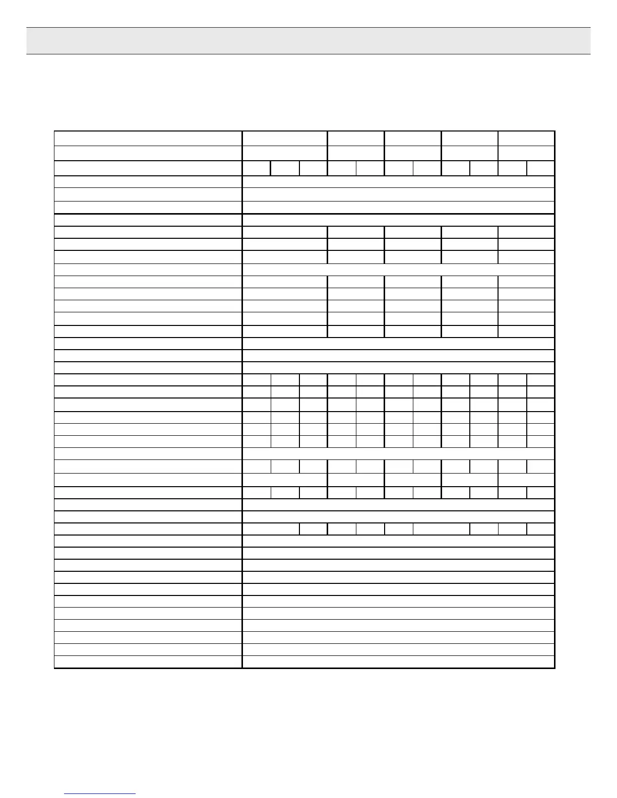
Technical Data 460V Class continued
Inverter Size 15 16 17 18 19
Recommended Motor Power[hp]15 20253040
Housing size EGHGHGHHRHR
Input Ratings
Supply voltage
[V]
305...500 ±0 (460 V Nominal voltage
)
Supply voltage frequency [Hz] 50 / 60 +/- 2
Input phases 3
Rated input current [A] 27 35 44 52 57
Recommended maximum input fuse [A] 35 40 60 60 70
Recommended wire gauge
1)
[awg]10 8664
Output Ratings
Rated output power [kVA] 17 23 29 35 42
Rated motor power [kW] 11 15 18,5 22 30
Rated output current [A] 21 27 34 40 52
Peak current (30 seconds)
2)
[A]36 49,5637590
Over current fault (E.OC) trip level [A] 43,2 59,4 75,6 90 108
Overload curve (see annex) 1
Output voltage [V] 3 x 0…Vsupply
Output frequency [Hz]
Generally 0 to 1600Hz (limited by control board and carrier frequency)
Rated switching frequency [kHz] 4 8 16 8 16 4 8 8 16 4 8
Maximum switching frequency [kHz] 16 16 16 16 16 16 16 16 16 16 16
Power loss at rated operation
3)
[W] 350 290 360 310 490 360 470 610 850 540 750
Stall current at 4kHz[A]2424243333424250506060
Stall current at 8kHz [A] 16 19 24 21.5 33 29,4 30 45 50 39 60
Stall current at 16kHz [A] 10 8.5 15 9.7 20 21 13.5 20 40 18 27
Braking Circuit
Min. braking resistance
4)
[Ohm]3939222522252213 9 13 9
Typ. braking resistance
4)
[Ohm]56 39282216
Max. braking current[A]2121373037303763886388
Installation Information
Max. shielded motor cable length
5)
[ft]
330
Tightening torque for terminal strip[in lb] 22112211 22 532253
Environmental
Max. heat sink temperature TOH [°C] 90°C / 194°F
Storage temperature [°C] -25...70 °C / -13…158°F
Operating temperature [°C] -10...45 °C / 14…113°F
Housing design / protection Chassis / IP20
Relative humidity max. 95% without condensation
Approvals
Tested in accordance with… EN 61800-3 /UL508C
Standards for emitted interference EN 55011 Class B / EN 55022 Class A
Standards for noise immunity IEC 1000-4-2 / -3 / -4 / -5/ -6
Climatic category 3K3 in accordance with EN 50178
11

 Loading...


