GB - 13
Description of the Terminals
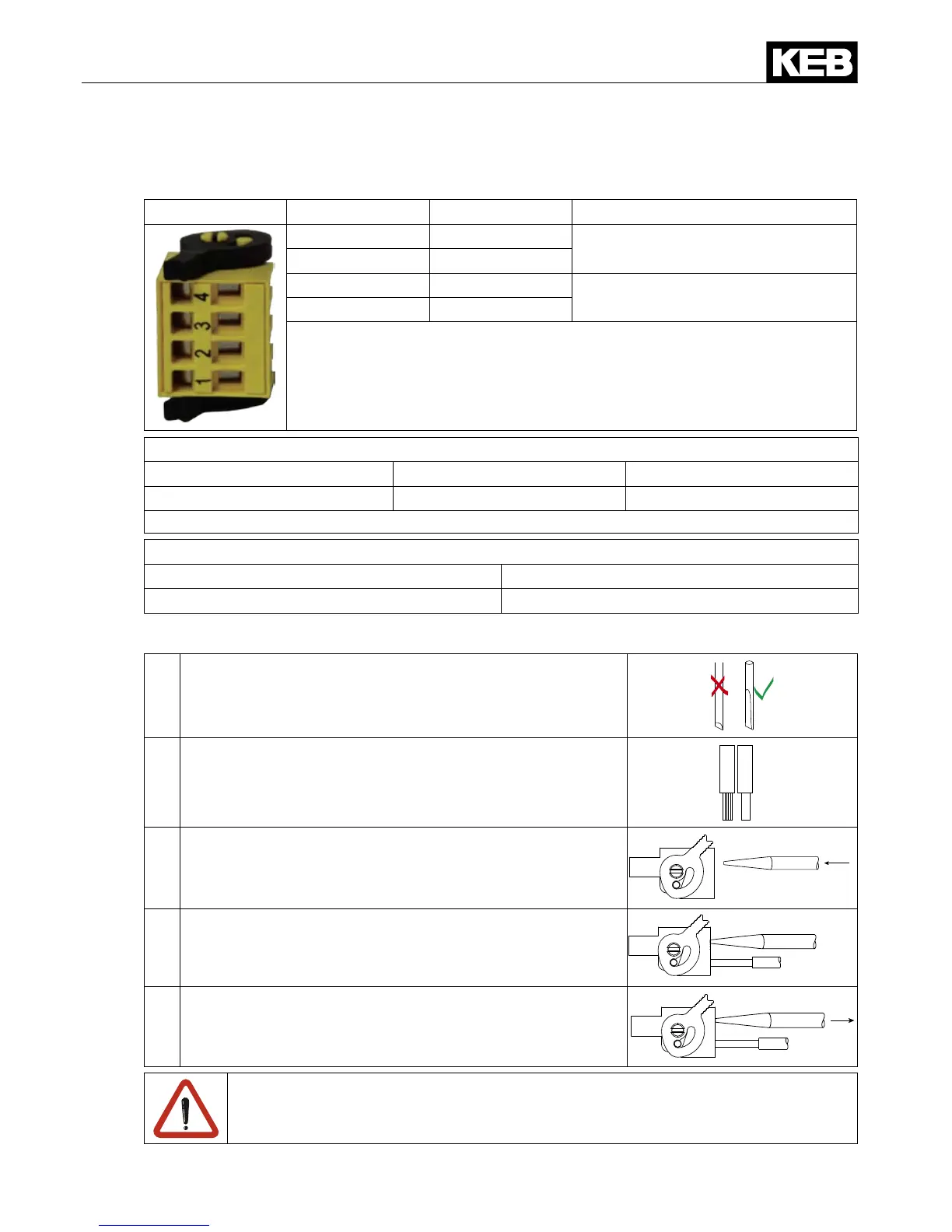
4. Description of the Terminals
X2B PIN Name I/O
1 STO1+
Input STO channel 1
2 STO1-
3 STO2+
Input STO channel 2
4 STO2-
The individual channels are designed potential-free, so 24V and 0 V can
be connected. The inputs are designed by way that safety switchgear
units with test pulse (OSSD signals) can be connected. The signals are
notevaluated,theyareonlyltered.TheOSSDtestintervalislimitedto
10ms.Theltertimefortheentirevoltagerangeis1ms.
Assembly of connecting wires with wire-end ferrules according to DIN46228/4
Cross-section / AWG Metal sleeve length Stripping length
0.2…0.75 mm
2
/ 24…19 6 mm 8 mm
Assemblyofconnectingwireswithoutwire-endferrules(rigidyandexible
Cross-section / AWG Stripping length
0.2…1.5 mm
2
/ 24…16 10 mm
4.1 Assembly of the wires
Required tools:
Screw driver SD 0.4 x 2.5 (DIN 5264)
1. Strip cable
Use wire-end ferrules as round, square or hexagon
pressing.
2. Plug screw driver mid into the square slot.
3. Plug cable into the round slot, that no wires can be seen
from the outside.
4. Removescrewdriverandcheckifcablesarexed.
A safe clamping can not be guaranteed when using shorter wire-end ferrules.

 Loading...


