GB - 16
Wiring Examples
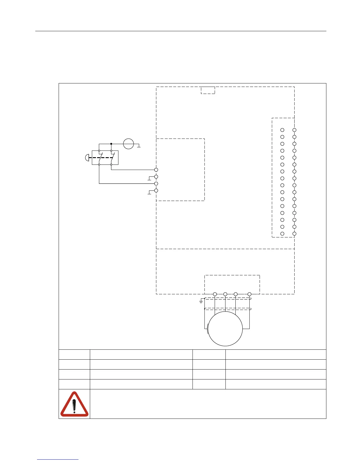
6. Wiring Examples
6.1 Direct switching off with emergency stop switch
U V W PE
M
X1A
X4A
1 - STO1+
2 - STO1-
3 - STO2+
4 - STO2-
X2B
+ -
24Vdc
2
4
6
8
10
12
14
16
18
20
22
24
26
28
30
32
X2A
1
3
5
7
9
11
13
15
17
19
21
23
25
27
29
31
①
②
③
①
Power Unit X1A Power terminal block
②
Control Circuit X2A Control terminal block
③
Safety component X2B STO terminal block
X4A Diagnostic interface
At operation of an emergency stop unit, when both contacts are connected to-
gether against a positive supply signal, make sure that there are no crossfaults.
The wiring must be suitable arranged.

 Loading...


