GB - 17
Wiring Examples
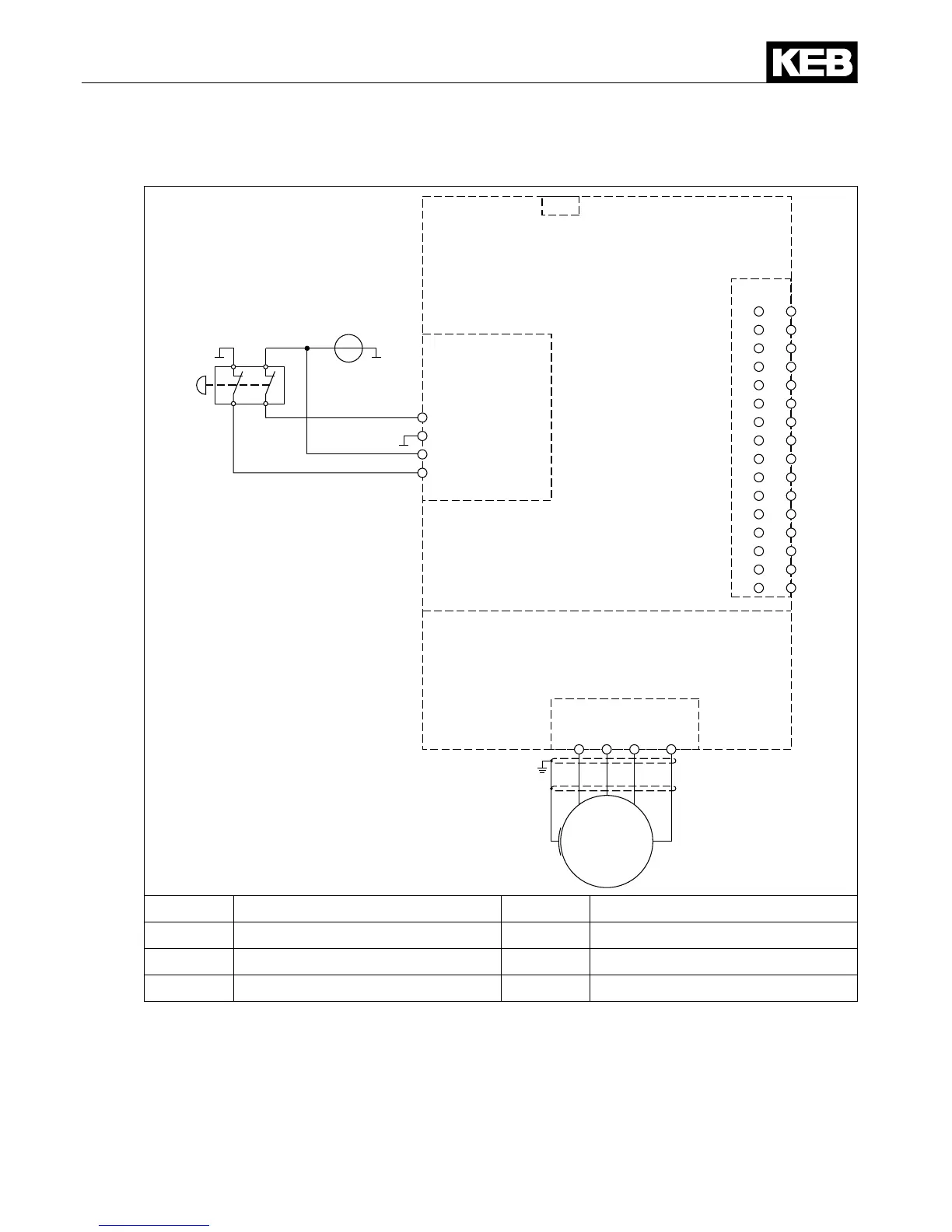
6.2 Direct switching off with emergency stop switch and monitoring of the wiring
U V W PE
M
X1A
X4A
1 - STO1+
2 - STO1-
3 - STO2+
4 - STO2-
+ -
24Vdc
2
4
6
8
10
12
14
16
18
20
22
24
26
28
30
32
X2A
1
3
5
7
9
11
13
15
17
19
21
23
25
27
29
31
X2B
①
②
③
①
Power Unit X1A Power terminal block
②
Control Circuit X2A Control terminal block
③
Safety component X2B STO terminal block
X4A Diagnostic interface
The displayed circuit shows wiring errors in the area of the emergency stop unit and supply
line. A possible short circuit on the primary side of the emergency stop switchgear (mass and
24 Vdc) and a short circuit on the secondary side of the unit or within the wiring leads either
directly or with closed contacts to a short circuit of the supply, whereby a series-connected
24V fuse triggers.
Besides the two displayed applications with an emergency stop switchgear, other sensors
(like door switches etc.) can be used similarly.

 Loading...


