GB - 19
Wiring Examples
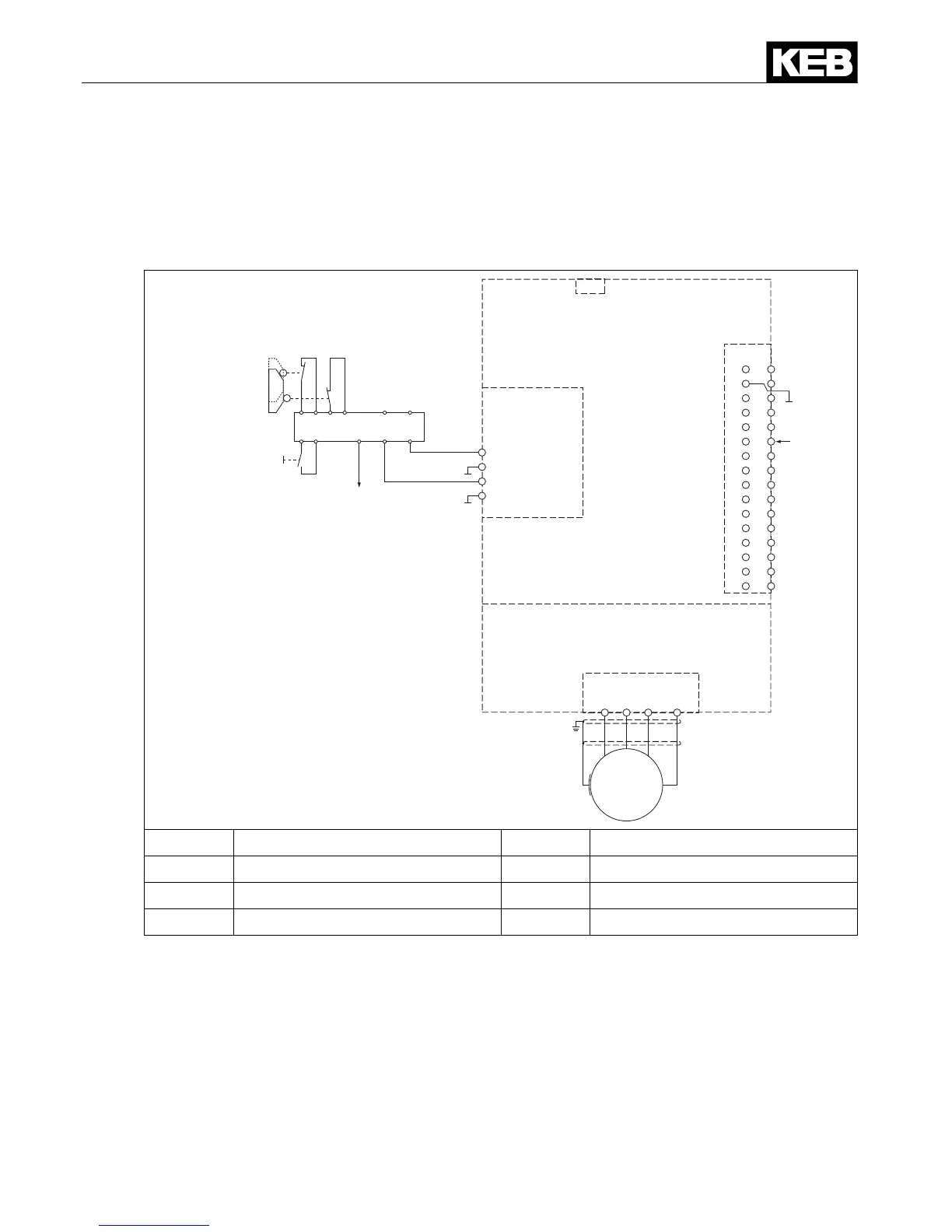
6.4 Wiring SS1
At tripping SS1 (Safe Stop 1) the drive is only disconnected from supply when it has reached
a standstill [IEC 61800-5-2]. The stop mode is not directly requested, but the maximum time
until reaching the standstill is estimated. This period is loaded in a safe time relay, which dis-
connectsthedrivenallyfromsupply.
U V W PE
M
X1A
X4A
1 - STO1+
2 - STO1-
3 - STO2+
4 - STO2-
S1 S2
X2A.12
(I3)
2
4
6
8
10
12
14
16
18
20
22
24
26
28
30
32
X2A
1
3
5
7
9
11
13
15
17
19
21
23
25
27
29
31
OPEN
CLOSED
Acknowledgment/
Quittung
X2B
①
②
③
④
④
①
Power Unit X1A Power terminal block
②
Control Circuit X2A Control terminal block
③
Safety component X2B STO terminal block
④
Safety module X4A Diagnostic interface
By activation of the emergency stop unit the drive is stopped with a deceleration ramp via
input X2A.12 (I3).
Simultaneously the expiration of the safe time occurs in the safety module. After expiration of
the safe period the control signals STO1 and STO2 (X2B.1 and 3) are removed and thus the
energy supply of the drive is disconnected.
The following adjustments must be done in COMBIVERT G6 for the function „drive stop“:

 Loading...


