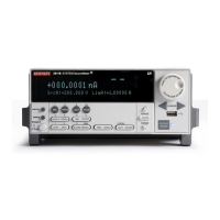
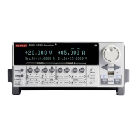
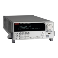
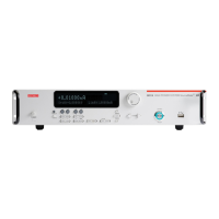
3: Functions and features Series 2600B System SourceMeter® Instrument
3-84 2600BS-901-01 Rev. B / May 2013
For a schematic diagram of the digital I/O hardware, refer to the Series 2600B Specifications on the
Keithley Instruments support website (http://www.keithley.com/support).
Connecting cables
Use a cable equipped with a male DB-25 connector (Keithley Instruments part number CA-126-1), or
a Model 2600-TLINK cable to connect the digital I/O port to other Keithley Instruments models
equipped with a Trigger Link (TLINK).
Digital I/O lines
The port provides 14 digital I/O lines. Each output is set high (+5 V) or low (0 V) and can read high or
low logic levels. Each digital I/O line is an open-drain signal.
The Models 2604B, 2614B, and 2634B do not have digital I/O lines.
+5 V output
The digital I/O port provides a +5 V VDC output that is used to drive external logic circuitry. Maximum
combined current output for all lines is 250 mA. These lines are protected by a self-resetting fuse with
a one hour recovery time.
Output enable line
The Model 2601B/2602B/2604B output enable (OE) line of the digital I/O can be used with a switch in
the test fixture or component handler. With proper use, power is removed from the DUT when the lid
of the fixture is opened. See the Using output enable
for more details.
The digital I/O port of the Model 2601B/2602B/2604B is not suitable for control of safety
circuits and should not be used to control a safety interlock. When an interlock is required
for safety, a separate circuit should be provided that meets the requirements of the
application to reliably protect the operator from exposed voltages.
Interlock line
At no time should you bypass the interlock feature of the Series 2600B. Safe operation
requires a separate interlock circuit that meets the requirements of the application to
reliably protect the operator from exposed voltages. Bypassing the interlock could expose
the operator to hazardous voltages that could result in personal injury or death.
The Model 2611B/2612B/2614B/2634B/2635B/2636B interlock (INT) line of the digital I/O can be
used with a switch in the test fixture or component handler. With proper use, power is removed from
the DUT when the lid of the fixture is opened. See Interlock (on page 3-89
) for more details.
Use interlock cable assembly CA-558 to connect the Series 2600B interlock to either a Model 8010
High Power Device Test Fixture or to the Model 2657A-LIM-3 LO Interconnect Module (refer to the
connection information supplied with the device).

 Loading...


