Section 3: Instrument description Series 3700A System Switch/Multimeter Reference Manual
3-28 3700AS-901-01 Rev. D/June 2018
The figure below shows the location of the ethernet connector on the Series 3700A rear panel.
Figure 31: Series 3700A ethernet connection
LAN status LEDs
The figure below illustrates the two status light emitting diodes (LED) that are on the LAN port of the
instrument. The table below the figure provides explanations of the LED states.
Figure 32: LAN status
LED indicates the LAN port is connected to a 100 Mbps network
LED indicates the LAN port is connected to a 10 Mbps network
is sending or receiving data
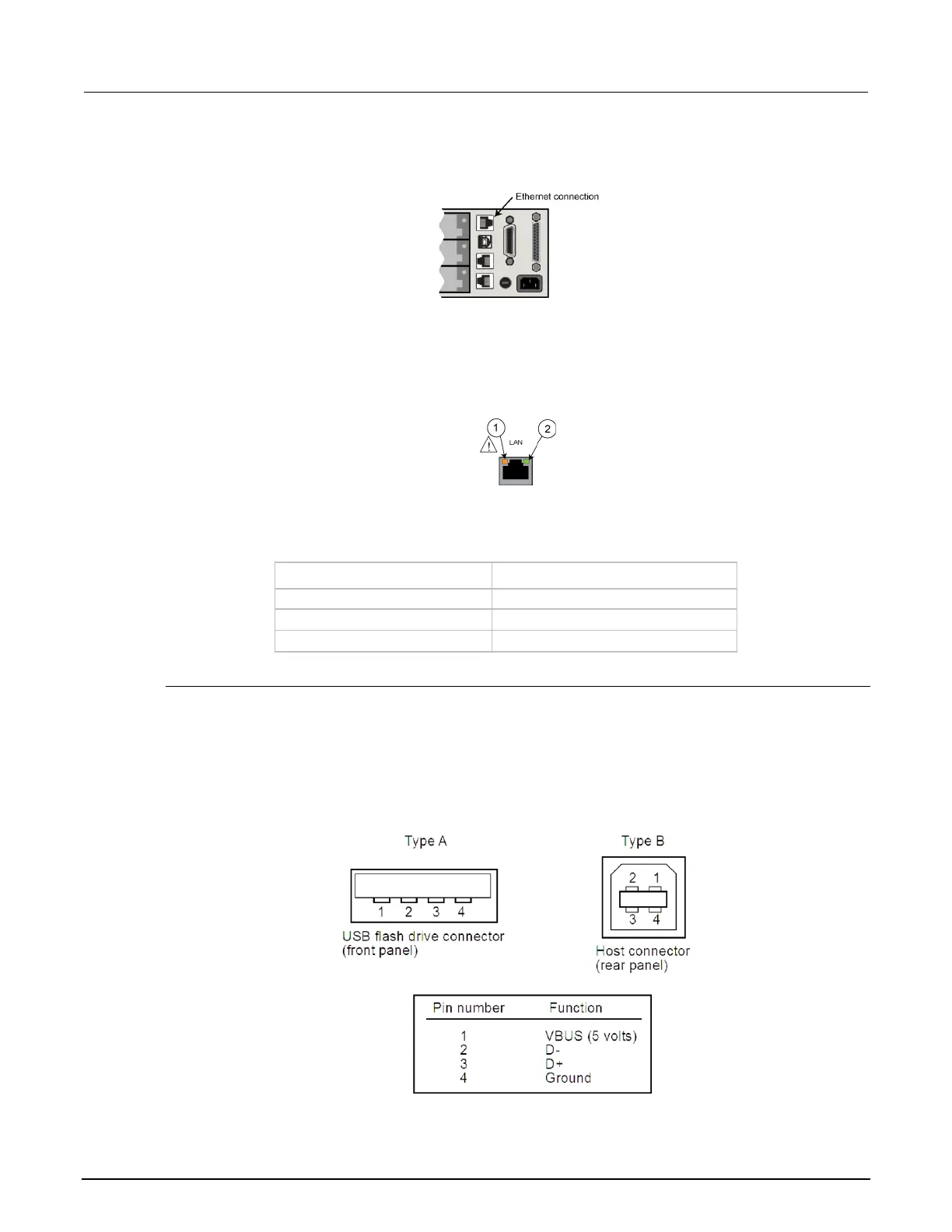
USB connectors
The downstream USB-2.0 receptacle (Type B) on the rear panel connects to a host. The front panel
has an upstream USB-2.0 connector (Type A) that connects to a user-supplied USB flash drive.
Use the rear connector to communicate with the instrument over USB by sending commands. Use
the front-panel connector to insert a USB flash drive for saving or loading reading buffers, user
setups, or scripts.
Figure 33: USB connectors