2: Performance verification Model DMM7510 7½ Digit Graphical Sampling Multimeter
2-34 DMM7510-905-01 Rev. A / April 2015
2. Set the calibrator to 0 V and enable the output.
3. Allow 5 minutes of settling time.
4. On the Model DMM7510, press the FUNCTION key and select DC voltage.
5. Press the HOME key.
6. Select Range and select 100 mV.
7. Press MENU key. Under Measure, select Settings.
8. Set Input Impedance to Auto.
9. Record the voltage offset reading.
10. Subtract the DCV 100 mV reading from the calibrator source value.
11. On the Model DMM7510, press the FUNCTION key and select Temperature.
12. Press MENU key. Under Measure, select Settings.
13. Set Thermocouple to Type J.
14. Set the Simulated Temperature to 0°C.
15. Set the output DC Voltage to value shown in the following tables.
16. Subtract the DCV 100 mV calibrator and cable offset voltage.
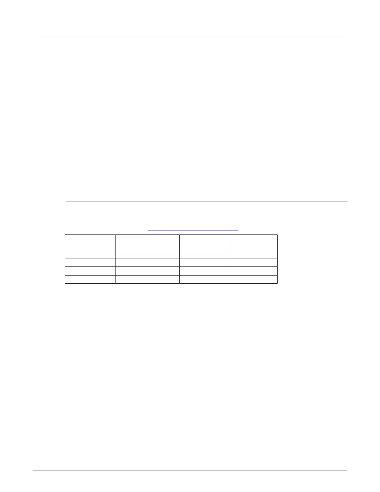
Verify the simulated thermocouple Type J temperature
Table calibrator source values based on NIST Monograph 175, reference data 60, version 2.0.
Use the following values to verify the performance of the Model DMM7510. Actual values depend on
published specifications (see Example reading limit calculation (on page 2-8
)).
Description Typical calibrator
source value
(V)
Lower limit Upper limit
-190 °C -7.659 E-03 -190.200 °C -189.800 °C
Simulated RTD temperature verification
Use the following to verify the performance of the Model DMM7510. Actual calibrator source values
will vary. RTD verification is based on the calibrator sourcing resistance and the Model DMM7510
conversion of the resistance measurement to calculated temperature based on the Callendar-Van
Dusen equation.
 Loading...


