EasyManua.ls Logo

Keithley SourceMeter 2612 User Manual

Keithley SourceMeter 2612
108 pages
To Next Page IconTo Next Page
To Previous Page IconTo Previous Page
Page #26 background image
1-14 Front Panel Operation Series 2600 System SourceMeters User’s Manual
2600S-900-01 Rev. A / May 2006 Return to In this section:
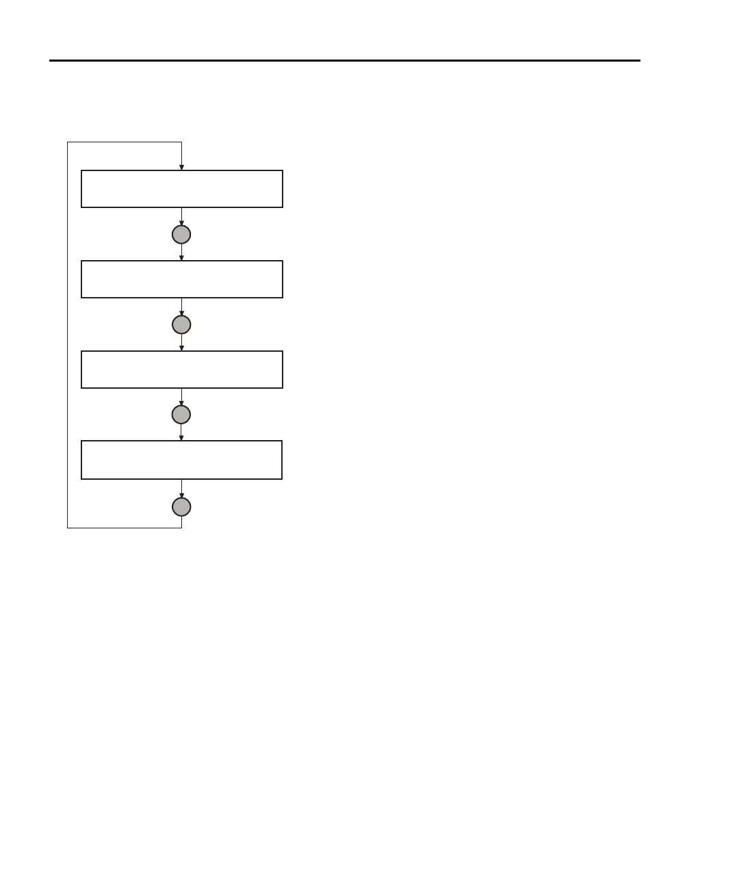
Figure 1-5
Display modes
User State
1.00000mA .    V
SrcA:+10.0000V SrcB:+000.000mV
1.00000mA
SrcA:+10.0000V LimA:10.0000mA
.    V
SrcB:+000.000mV LimB:100.000mA
Press DISPLAY key
Press DISPLAY key
Press DISPLAY key
Press DISPLAY key
Source-Measure display for SMU A and SMU B:
Top line displays the measure function (V, A, W or W).
Bottom line displays the source function (V or A)
and level.
Source-Measure and Compliance Limit display for SMU A:
Top line displays the measure function (V, A, W or W).
Bottom line displays the source function (V or A) and level,
and the compliance limit (A or V).
Source-Measure and Compliance Limit display for SMU B:
Top line displays the measure function (V, A, W or W).
Bottom line displays the source function (V or A) and level,
and the compliance limit (A or V).
Display for user-defined messages and prompts.
     Indicates that a measured reading has not been
triggered.

Table of Contents

Other manuals for Keithley SourceMeter 2612

Question and Answer IconNeed help?

Do you have a question about the Keithley SourceMeter 2612 and is the answer not in the manual?

Keithley SourceMeter 2612 Specifications

General IconGeneral
Model2612
TypeSourceMeter
Channels2
Measurement Resolution6.5 digits
Power Output100 W
Current Source Range±3 A
Maximum Power100W
Voltage Measurement Resolution100 nV (6.5 digits)
Current Measurement Resolution10pA
InterfaceGPIB, USB, Ethernet

Summary

Warranty Information

Warranty Terms and Limitations

Details product warranty coverage, duration, and conditions for validity.

Safety Precautions

User Roles and Electrical Safety

Defines user roles and essential electrical safety practices.

Front Panel Operation

Instrument Power-Up and Basic Measurements

Steps for powering up the instrument and performing initial measurements.

Remote Operation

Test Script Builder Usage

Guide to the TSB software for creating, running, and managing scripts.

Test Script Processor (TSP) Interaction

Controlling Multiple SourceMeters (TSP-Link)

TSP-Link System Setup and Operation

Connecting, configuring, and using multiple instruments via TSP-Link.

Appendix B: Frequently Asked Questions (FAQs)

Advanced Channel Configurations

Connecting channels in series for higher voltage and in parallel for higher current.

Related product manuals