EN
5. USING CONTROL PANELS
5.1 Regular control panel
DYNAMICS
U
W006169
2T / 4TGAS
MIG
HOT SPOT
SPOT /
CYCLE
POST GAS
m
min
MANUAL
4T
V
1. 2. 3.
4. 5. 6. 7.
8.
9.
10.
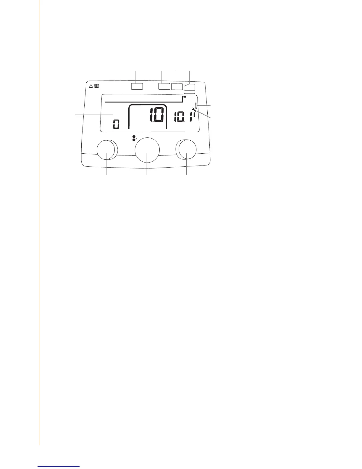
Models featuring the regular (R) control panel oer the following control functions and
features.
1. Control knob for welding dynamics
2. Control knob for wire feed speed
3. Control knob for welding voltage
4. Shielding gas button
5. Timer button for spot welding and cycle arc welding
6. 2T/4T gun switch latching button
7. Selection for MIG/MAG or HOT SPOT function
8. Parameter display
9. Overheating indicator
10. WireLine service indicator
1. Control knob for welding dynamics
Dynamics function controls the rate of rise of current when the ller wire is in short circuit
with the welding plate. This control adjustment is necessary due to the alternative welding
parameters, materials, wire sizes, gas types and current values used.
The welding dynamics scale is –9 to +9. Negative values make the rise of current slower, which
results in a hotter and more uid weld characteristic. Positive values make the rise of current
faster, which results in a colder welding condition. This can result in more spatter during
welding depending on the ller wire size and type used.
How to nd the optimal dynamics setting?
Start by setting ‘0’ and make a test weld after selecting the correct wire feed speed and
voltage values. Fine tune the welding arc by trying dierent values in the negative (-) and
positive (+) sides of the dynamics scale.
2. Control knob for wire feed speed
This control knob increases and reduces the speed of ller wire delivery to the welding arc.
The scale is regulated in meters per minute. There is also a graphical display bar indicating the
proportion of motor speed selected.
Kempact 251R, 253R, 323R, 181A, 251A, 253A, 323A
18

 Loading...