(No.RA018<Rev.002>)1-41
4.4 BER (Bit Error Rate) Measurement
(1) The Panel Test Mode is used to measure the BER (Refer
"4.2.1 Test mode operation features").
(2) Select "10" (P25 Phase1), "7" (P25 Phase2) and "7"
(NXDN Mode) for test signaling (Refer to "4.2.3 Frequency
and Signaling" (2) Test signaling).
Note:
"7" (NXDN Mode) can be selected only by PC test mode.
(3) Select a bandwidth (Narrow/Very Narrow) by pressing the
[ ] key. When P25 Phase1 or P25 Phase2 is selected, it
is not necessary to select a bandwidth.
(4) Select a test frequency ("4.2.3 Frequency and Signaling"
(2) Test signaling Test frequency).
(5) Measure the BER (Bit Error Rate) using the digital radio
tester.
Enter a standard input signal into the transceiver as a stan-
dard tone test pattern for P25, FSW+PN9 for NXDN.
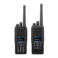
(6) Adjust the input signal level to achieve the standard bit er-
ror rate (BER).
(For example, if the BER is 0.86%, the display shows
"0.86".)
Note:
"4", "9" (P25 Phase1), "2" (P25 Phase2) is for production.
4.5 Adjustment points
4.6 Test Equipment Required for Alignment
* The test equipment which is not used for adjustment is contained in this table.
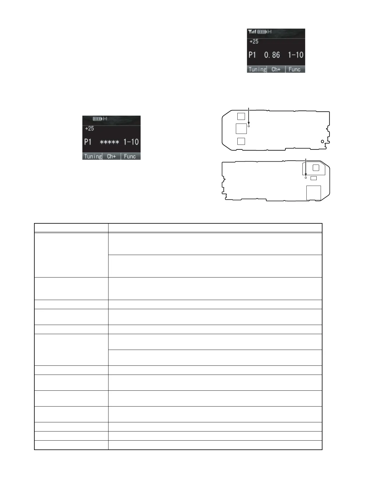
MAIN UNIT (XC1-033, XC1-036)
Component side
RTC (CN710)
MAIN UNIT (XC1-033, XC1-036)
Foil side
RTC (CN709)
Test Equipment Major Specifications
1. Standard Signal
Generator (SSG)
Frequency Range
Modulation
Output
100 to 900MHz
Frequency modulation and external modulation
-127dBm/0.1uV to greater than -20dBm/22.4mV
When performing the Frequency adjustment, the following accuracy is necessary.
• 0.003ppm
Use a standard oscillator for adjustments, if necessary.
2. Power Meter Input Impedance
Operation Frequency
Measurement Capability
50Ω
100 to 900MHz
Vicinity of 10W
3. Deviation Meter Frequency Range 100 to 900MHz
4. Digital Volt Meter
(DVM)
Measuring Range
Input Impedance
10mV to 10V DC
High input impedance for minimum circuit loading
5. Oscilloscope DC through 30MHz
6. Frequency Counter Frequency Range
Frequency Stability
10Hz to 1000MHz
0.2ppm or less
To measure the oscillating frequency of the internal clock 32766.00Hz~32770.00Hz for
RTC Correction Resolution 0.01Hz is better for accuracy adjustment.
7. Ammeter 5A
8. AF Volt Meter (AF VM) Frequency Range
Voltage Range
50Hz to 10kHz
1mV to 10V
9. Audio Generator (AG) Frequency Range
Output
50Hz to 5kHz or more
0 to 1V
10. Distortion Meter Capability
Input Level
3% or less at 1kHz
50mV to 10Vrms
11. Spectrum Analyzer Measuring Range DC to 1GHz or more
12. 8Ω Dummy Load Approx. 8Ω, 3W
13. Regulated Power Supply 5V to 10V, approx. 3A, Useful if ammeter equipped
 Loading...