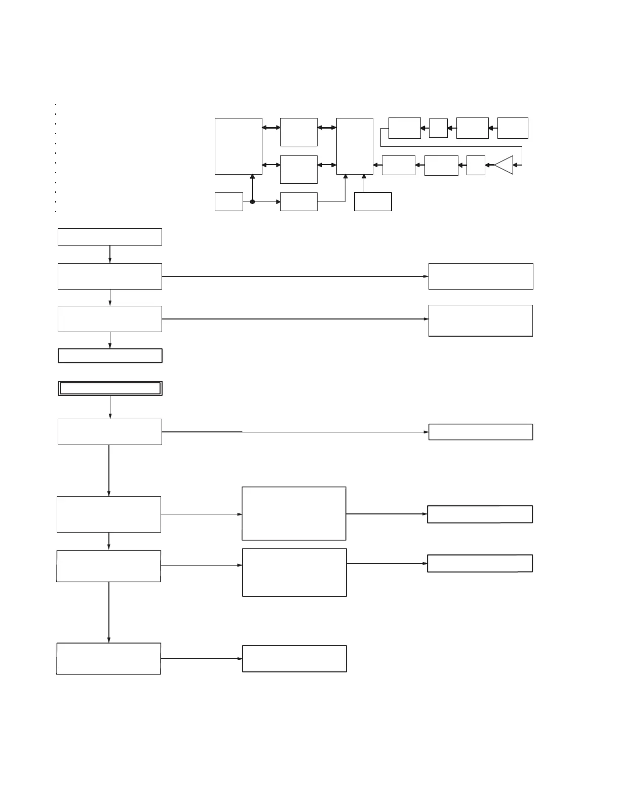
Positioning is not carried out normally.
Suitable location for the receive the
GPS signal ?
Verify the contact of the GPS internal
antenna with the PCB.
No
Yes
GPS antenna (Connect on CN907)
LNA IC (IC851)
Pre-SAW Filter (L857)
Post-SAW Filter (L853)
Bluetooth/GPS IC (IC850)
Level conversion IC (IC852, IC853)
TCXO 19.2MHz (X700)
Clock Buffer (IC700)
32.768 KHz clock (X850)
33BT Regulator (IC38)
18BT Regulator (IC37)
MPU/DSP IC (IC702)
Re-assembling the GPS antenna
correctly.
If an antenna is defective, replace the
GPS internal antenna.
Replace any abnormal parts.
Verify the BT/GPS power
supply.
IC702
IC852
IC850 L857 Shee t metal
UART UART
IC853
L853
IC851
PCM PCM
LNA
X700
IC700
X850
MPU/DSP
IC
BT/GPS
IC
TCXO
19.2MHz
32.768 kHz
Clock
ANT
Match ing
GPS
Antenn a
Clock
Buffer
Level
conversion
IC
Level
conversion
IC
HPF
Pre-SAW
Filter
Post-SAW
Filter
RF
Match ing
ATT
Operate at place where is good visibility
of the sky.
Check the PCB side A.
Check the PCB side A.
Verify the ANT Matching Parts.
Visual check of L905, C948, C883
(Whether not damaged)
[The BT/GPS power supply line
33BT circuit is faulty]
C856, C860, C861, C870, L862,
C885, C890
Replace any abnormal parts.
Check the PCB side B (a).
Verify the BT/GPS power
supply.
[The BT/GPS power supply line
18BT circuit is faulty]
C859, C852, C868, L861, C891, C844
Replace any abnormal parts.
Check the PCB side B (b).
Verify the BT/GPS control
signal (/BT_SHUTDOWN).
[MPU/DSP (IC702) is faulty]
Replace the PCB.
(33BT) L862: 3.3V
(18BT) L861: 1.8V
R853: 1.8V
When an abnormal
condition is confirmed.
When an abnormal
condition is confirmed.
When an abnormal
condition is confirmed.
When an abnormal
condition is confirmed.
When an abnormal
condition is confirmed.
When an abnormal
condition is confirmed.
When an abnormal
condition is confirmed.
Visual check of the PCB side A parts
(Whether not damaged).
Visual check of the PCB side A parts.
(Whether not damaged)
When a normal
condition is confirmed.
When a normal
condition is confirmed.
When a normal
condition is confirmed.
When a normal
condition is confirmed.
When a normal
condition is confirmed.
Major parts for a GPS circuit
 Loading...