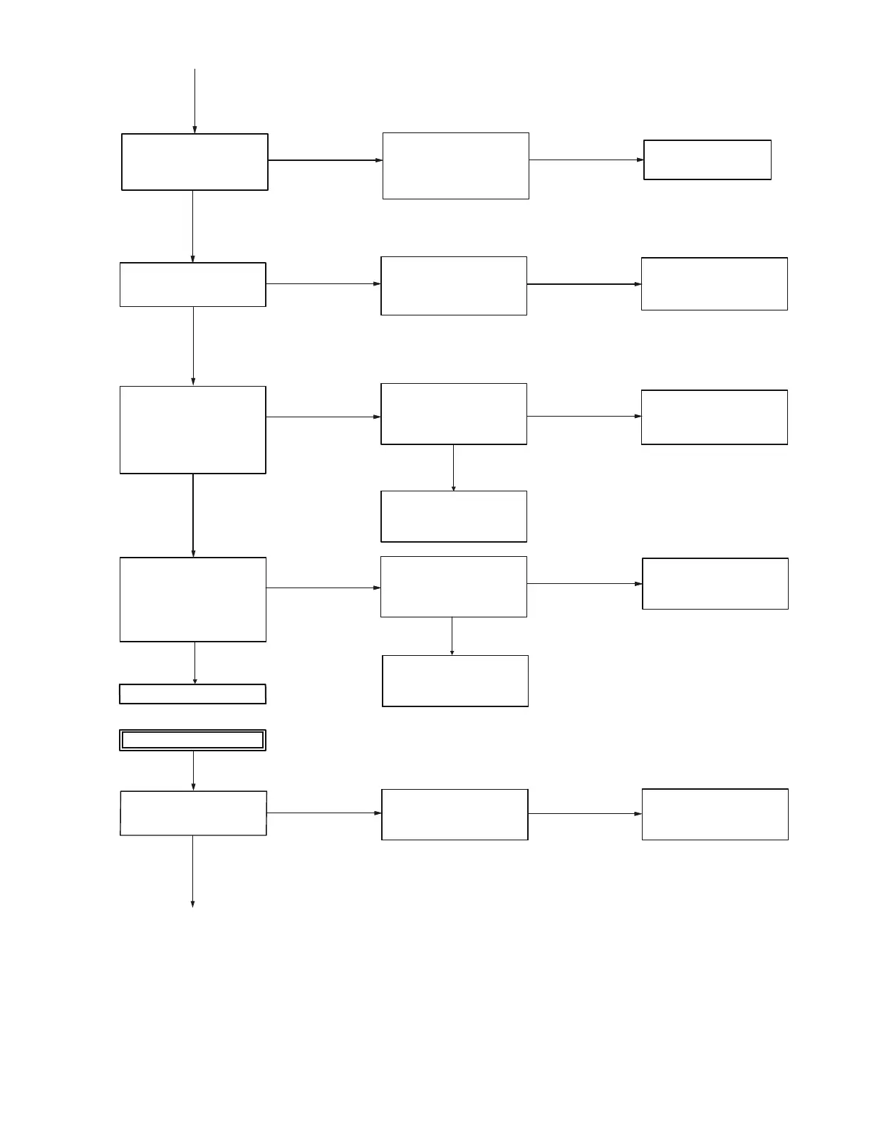
Verify the reference clock for the BT/GPS.
(BT_CLK) Intersection of
C850 and R861: Sine waveform,
19.2MHz, 0.2 to 1.2 Vp-p
[The reference clock circuit
for the BT/GPS is faulty].
Verify the BT/GPS control
signal (RXD2).
CP851 (1 pin): Square waveform
UART data of 3.3V logic.
Baud rate:
Default: 115.2kbps
After: 3.967Mbps.
Check the PCB side B (c).
Verify the BT/GPS control
signal (TXD2).
CP851 (2 pin):
Square waveform UART data
of 3.3V logic.
C850, R861, R862.
Replace any abnormal parts.
Verify the LNA power supply
VDD_TCXO (G1 pin) of IC850
(Intersection of C855 and R862): 1.8V
[The power supply line circuit
for LNA is faulty]
Replace any abnormal parts.
[VDD_TCXO (G1 pin) of
IC850 is faulty]
Replace the PCB
Verify the BT/GPS control
signal (18BT_HCI_RX).
IC852 (8 pin):
Square waveform UART data
of 1.8V logic.
Baud rate:
Default: 115.2kbps
After: 3.967Mbps.
[MPU/DSP (IC702) is faulty]
Replace the PCB.
[The 18BT_HCI_RX (TXD2)
line circuit is faulty]
Verify the BT/GPS control
signal (18BT_HCI_TX).
IC852 (8 pin):
Square waveform UART data
of 1.8V logic.
[BT/GPS IC (IC850) is faulty]
Replace the PCB.
Check the PCB side B.
Check the PCB side B.
[The RXD2 (18BT_HCI_TX)
line circuit is faulty]
Replace the CP851, IC852, R858.
Verify the LNA ENABLE.
IC851 (6 pin): 1.8V
[The LNA ENABLE line is faulty]
Visual check of the R860
(Whether not damaged).
Replace any abnormal parts
[GPS_EXT_LNA_EN
(H6 pin) of IC850 is
faulty]
Replace the PCB.
When a normal
condition is confirmed.
When a normal
condition is confirmed.
When a normal
condition is confirmed.
When a normal
condition is confirmed.
When a normal
condition is confirmed.
When a normal
condition is confirmed.
When a normal
condition is confirmed.
When an abnormal
condition is confirmed.
When an abnormal
condition is confirmed.
When an abnormal
condition is confirmed.
When an abnormal
condition is confirmed.
When an abnormal
condition is confirmed.
When an abnormal
condition is confirmed.
When an abnormal
condition is confirmed.
When an abnormal
condition is confirmed.
When an abnormal
condition is confirmed.
When an abnormal
condition is confirmed.
When a normal
condition is confirmed.
When a normal
condition is confirmed.
Visual check of the PCB side A parts
(Whether not damaged)
Visual check of the C855, R862 and
R851 (Whether not damaged).
Replace the CP851, IC852, R858.
 Loading...