HPF parts: C882, C881, C880, L859, L858
Pre-SAW parts: L857, D850, D851
LNA parts: C879, L856, C878, IC851, C876, C877, C874, R860
ATT parts: R857, R856, R855
Post-SAW parts: L853, GPS IC RF Matching parts: C867, C866, L852
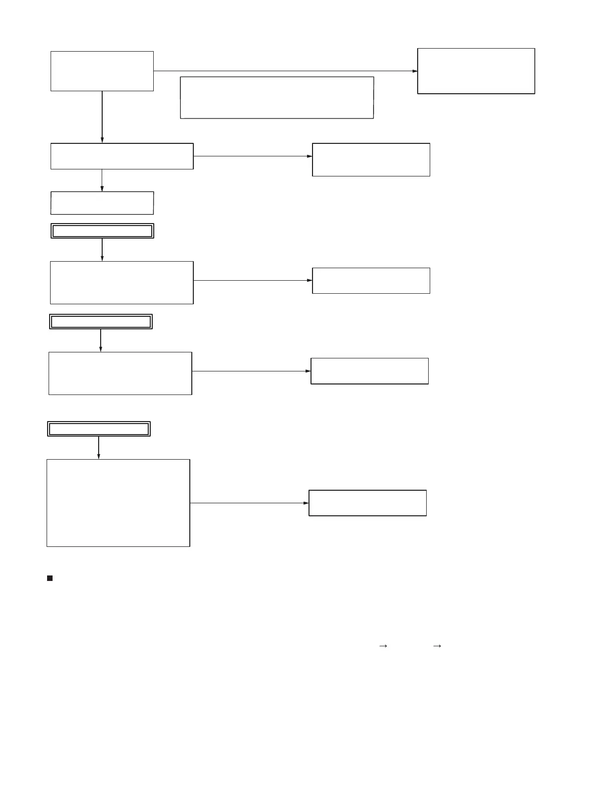
Verify the RF input circuit for the GPS.
HPF, Pre-SAW, LNA, ATT, Post-SAW,
GPS IC RF Matching.
[The GPS RF input circuit is faulty]
Replace the GPS RF input circuit
parts. (only the parts which can be
replaced.) If any unexchangeable
parts are abnormal, replace the PCB.
Verify the RTC for the BT/GPS.
X850 (3 pin): Square waveform, 32.768 kHz,
1.8Vp-p
Replace any abnormal parts.
[The BT/GPS IC is abnormal]
Replace the PCB.
Check the PCB side B (a).
[The BT/GPS power supply line 33BT circuit is faulty]
Visual check of the PCB side B parts
(Whether not damaged).
IC39, IC38, C55, L850
Replace any abnormal parts.
[The BT/GPS IC is abnormal]
Replace the PCB.
Check the PCB side B (b).
[The BT/GPS power supply line 18BT circuit is faulty]
IC37, L38, C52, C53, L851, L854, C875
Replace any abnormal parts.
[The BT/GPS IC is abnormal]
Replace the PCB.
Check the PCB side B (c).
[The BT/GPS IC is abnormal]
Replace the PCB.
[The reference clock circuit for the BT/GPS is faulty]
Verify the PCB side B parts
X700 (OUTPUT pin): Clipped sine wave,
X700 (VCC pin): 3.3V,
R700, R702, C701, C702, R704, C703, R705,
R706, R780,
Q700 (B, E): Clipped sine wave, Q700 (C): 3.3V,
R707, C704, C706, R708, C705, L701, C707,
R772, C708
Replace any abnormal parts.
If any unexchangeable parts are abnormal,
Descriptions of signal names
1) 33BT: BT/GPS IC 3.3V power supply
2) 18BT: BT/GPS IC 1.8V power supply
3) TXD2: BT/GPS serial data line connected to UART TX of MPU/DSP IC (MPU/DSP to BT/GPS IC)
4) RXD2: BT/GPS serial data line connected to UART RX of MPU/DSP IC (MPU/DSP to BT/GPS IC)
5) 18BT_HCI_RX: BT/GPS serial data line connected to UART RX of BT/GPS IC (MPU to BT/GPS IC)
6) 18BT_HCI_TX: BT/GPS serial data line connected to UART TX of BT/GPS IC (BT/GPS IC to MPU)
7) /BT_SHUTDOWN: BT/GPS active control of MPU/DSP IC (MPU/DSP to BT/GPS IC) High Active, Low Reset
replace the PCB.
When a normal
condition is confirmed.
When a normal
condition is confirmed.
When a normal
condition is confirmed.
When a normal
condition is confirmed.
When a normal
condition is confirmed.
When an abnormal
condition is confirmed.
When an abnormal
condition is confirmed.
When an abnormal
condition is confirmed.
When an abnormal
condition is confirmed.
When an abnormal
condition is confirmed.
Visual check of the RTC line circuit for the
BT/GPS (Whether not damaged).
X850, L854, C875
Visual check of the PCB side B parts.
(Whether not damaged).
 Loading...