1-66 (No.RA018<Rev.002>)
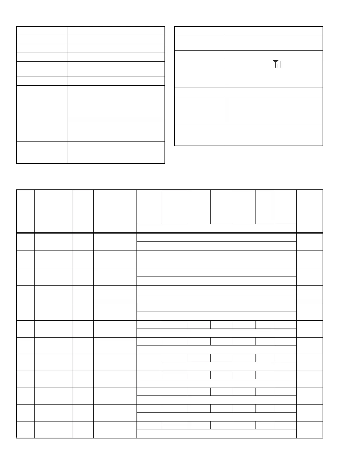
4.13.5 Adjustment item and Display
DQT Deviation DQT deviation is adjusted.
LTR Deviation LTR deviation is adjusted.
DTMF Deviation DTMF deviation is adjusted.
Single Tone Devia-
tion
The deviation of Single Tone used in “2-
tone” is adjusted.
MSK Deviation MSK tone deviation is adjusted.
CWID Deviation CWID tone deviation is adjusted.
CWID is used to inform the others who is
transmitting on a 6.25-kHz spacing chan-
nel. (In FCC rule, Analog mode or CWID
is required for each channel-spacing.)
Sensitivity 1 Band-Pass Filter is adjusted.
The performance of Receive Sensitivity is
improved.
Sensitivity 2 Band-Pass Filter is adjusted.
The performance of Receive Sensitivity is
improved.
Adjustment Item Description
RSSI Reference The minimum RSSI level for scan stop is
adjusted.
Open Squelch The squelch level at level “1” is adjusted.
Low RSSI RSSI display level “ “ is adjusted.
Both “Low RSSI” and “High RSSI” must
be adjusted. (The curve data of RSSI lev-
el is applied.)
High RSSI
Tight Squelch The squelch level at level “9” is adjusted.
Battery Warning
Level
Battery Warning Level (LED blinking lev-
el) is adjusted.
Battery Warning Level minus 0.4V is the
transmission inhibited level.
Internal Microphone
Gain
Internal Microphone Gain is adjusted.
This item can be adjusted only in PC Test
Mode.
Adjustment Item Description
Order Adjusutment
item
Main
LCD
display
Sub LCD
display
Aw
(Analog
Wide 5k)
As
(Analog
Wide 4k)
An
(Analog
Narrow)
P1
(P25
Phase1)
P2
(P25
Phase2)
Nn
(NXDN
Nar-
row)
Nv
(NXDN
Very
Nar-
row)
Adjust
item
Number
Adjustment range
1 Receive Assist RAST (CV voltage)
9 point ADJ
Common
Section 2
1
~ 4096
2 Transmit Assist TAST (CV voltage)
9 point ADJ
Common
Section 3
1
~ 4096
3 RTC Correction RTC -
-
Common
Section 5
-2.00~-0.01 ,0.00 ,+0.01~+2.00
4 Ramp Up Offset RAMPU (ADC measurement
value)
-
Transmitter
Section 1
1~1024
5 Ramp Down
Offset
RAMPD (ADC measurement
value)
-
Transmitter
Section 2
1~1024
6 High Transmit
Power
H_PWR - - - 5 - - - - Transmitter
Section 3
1~1024
7 Medium Transmit
Power
M_PWR - - - 5 - - - - Transmitter
Section 4
1~1024
8 Low Transmit
Power
L_PWR - - - 5 - - - - Transmitter
Section 5
1~1024
9 Balance BAL (Encode frequency) - - 5 - - - - Transmitter
Section 6
1~1024
10 Maximum
Deviation
ADEV - 5 5 5 - - - - Transmitter
Section 7
1~1024
11 P25 High
Deviation
PDEV - - - - 5 - - - Transmitter
Section 8
1~1024
12 P25 H-CPM
Deviation
P2DEV - - - - - 5 - - Transmitter
Section 9
1~1024
 Loading...