This document describes the KD716 E-bike Intelligent LCD display, providing a comprehensive overview of its functions, technical specifications, usage, and maintenance.
Function Description
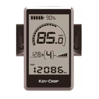
The KD716 display is designed to meet various cycling needs by providing a range of indications and settings. It features an intelligent battery power indicator, motor power display, and assist level indication. Cyclists can monitor their speed (current, maximum, and average), ODO (odometer), and Trip km (trip distance). Additional functions include push assist, trip time, clock, backlight control, error code indication, pedal frequency, and optional USB connection and remaining range indication. The display also allows for various parameter settings, such as wheel diameter, speed limit, battery level bar settings, assist level settings, power-on password settings, and controller over-current cut settings. A feature to recover default settings is also included.
Important Technical Specifications
- Power Supply: 24V/36V/48V
- Rated Working Current: 10mA
- Maximum Working Current: 30mA
- Off-state Leakage Current: <1μΑ
- Operating Temperature: -20℃ to 60℃
- Storage Temperature: -30℃ to 70℃
- Wheel Diameter Settings (Ld): Optional values include 16, 18, 20, 22, 24, 26, 700C, and 28 inches. The default is 26 inches.
- Speed Limit Settings (LS): Ranges from 12 Km/h to 40 Km/h. The default is 25 Km/h.
- Controller Over-Current Cut Settings (CUR): Ranges from 7.0A to 22.0A. The default is 15A.
- PAS Magnet Numbers (n): Default value is 6.
- Speed Sensor Magnet Heads (SPS): Ranges from 1 to 15. Default value is 1.
- Battery Power Delay Time (DLY): Options include 3s, 6s, 12s. Default is 3s.
- Maximum Speed Limit (MAX SPD): Ranges from 25 Km/h to 40 Km/h. Default is 40 Km/h.
Usage Features
General Operations:
- Switching E-bike System ON/OFF: Press the remote power button to switch on. Hold for 2 seconds to switch off. The system automatically switches off after 10 minutes of inactivity.
- Display Interface: By default, it shows current speed and trip distance. Pressing the "i" button cycles through Trip Distance (Km), ODO (Km), Max. Speed (Km/h), Ave. Speed (Km/h), and Trip Time (Min.).
- Switching Push-assist Mode ON/OFF: Press and hold the "-" button for 2 seconds to activate push assist at 6 Km/h. Release the button to deactivate. This mode is only for pushing the E-bike, not riding.
- Switching Lighting ON/OFF: Hold the UP button for 2 seconds to turn on the display backlight and headlight. Hold again for 2 seconds to turn them off.
- Power Assist Level: Use the "+" or "-" buttons to change the assist level from 0 (zero output) to 5 (maximum power). The default is level 1. The display blinks at 0 or 5 to indicate minimum or maximum power, respectively.
- Battery Power Indicator: Five bars represent battery capacity. The frame flashes at 1Hz when the battery is low, indicating a need for recharge.
- Motor Power Indication: Displays motor power in digits.
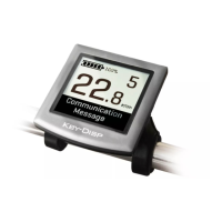
- Error Code Indication: Shows error codes when faults occur in the E-bike's electronic control system. Refer to Attached list 1 for definitions.
General Settings (accessed by holding '+' and '-' for 2 seconds when parked):
- Trip Distance Clearance (TC): Select Yes or No to clear the single ride distance.
- Backlight Settings (bL): Levels 1 (lowest), 2 (medium), and 3 (highest). Default is 1. Use UP/DOWN buttons to adjust.
- Unit Conversion (U): "1" for miles, "2" for kilometers. Default is 2. Use UP/DOWN buttons to adjust.
Personalized Parameter Settings (accessed by holding UP and DOWN for 2 seconds twice when parked):
- Battery Power Bar Settings (VOL): Set voltage values for each of the 5 battery bars. Default for VOL 1 is 31.5V.
- Power Assist Level Settings (optional): Choose from 8 PAS level modes (e.g., 0-3, 1-3, 0-5, 1-5, 0-7, 1-7, 0-9, 1-9). Default is 0-5.
- PAS Ratio Settings: Adjust the speed ratio for each PAS level. For example, level 1 ratio ranges from 45-55%, with a default of 50%.
- Controller Over-Current Cut Settings (CUR): Adjust the current value.
- PAS Sensor Settings (optional):
- PAS Direction Settings: "run-F" (forward) or "run-b" (backward). Default is "run-F".
- PAS Sensitivity Settings (SCN): Ranges from "2" (strongest) to "9" (weakest). Default is "2".
- Magnet Quantity Settings (n): Adjust the number of magnets on the PAS disk. Default is 6.
- Speed Sensor Settings (optional) (SPS): Adjust the quantity of magnet heads (1 to 15). Default is 1.
- Throttle Functions (optional):
- Throttle Push Assist Enable/Disable (HL): HL-N (disabled) or HL-Y (enabled). Default is N.
- Throttle Level Enable/Disable (HF): HF-Y (throttle speed limited by current PAS level) or HF-N (throttle speed not limited by current PAS level). Default is N.
- System Settings (optional):
- Delay Time Settings for Battery Power (DLY): Adjust delay time (3s, 6s, 12s). Default is 3s.
- Max Speed Limit Settings (MAX SPD): Set maximum speed from 25 Km/h to 40 Km/h. Default is 40 Km/h.
- Push-assist Button Enable/Disable (PUS): Y (enable) or N (disable). Default is Y.
- Slow Start Up Settings (SSP): Ranges from "1" to "4" (slowest). Default is "1".
- Power-on Password Settings:
- Power-on Password Enable/Disable: Y (enable) or N (disable). Default is N.
- Power-on Password Modifications: Change the 4-digit password (default "1212").
Exit Settings:
- Press "i" (less than 2s) to confirm and save settings.
- Hold "i" (more than 2s) to store settings and exit.
- Hold DOWN (more than 2s) to cancel operations without saving and exit.
- The display automatically exits settings if there's no operation for one minute.
Recover Default Settings (dEF):
- Hold UP and "i" for 2 seconds to access. Choose "Y" to recover default settings or "N" to not. If "Y" is chosen, hold "i" for 2 seconds to confirm, and the display shows DEF-00 before returning to the start-up interface.
Maintenance Features
Quality Assurance and Warranty Scope:
- Warranty: Valid for 24 months after shipment or delivery, under normal usage conditions.
- Exclusions: Warranty does not cover demolished displays, damage from wrong installation/operation, broken shells after factory departure, broken cables, issues beyond the warranty period, or damage due to force majeure (e.g., fire, earthquake).
Wire Connection Layout:
- The manual provides a wire sequence table for connection to the controller and display end.
- 1: Red (VCC) - +
- 2: Blue (K) - Lock
- 3: Black (GND) - -
- 4: Green (RX) - RX
- 5: Yellow (TX) - TX
- Note: Some products use waterproof connectors, so wire colors may not be visible in the harness.
Warnings:
- Use the display with caution. Do not attempt to release or link the connector when the battery is powered on.
- Avoid hitting the display.
- Do not modify system parameters to prevent parameter disorder.
- If an error code appears, have the display repaired.