CIM-LINK
J3 ON – Global Master
J4 ON – Single ACU Mode
ACU
Input A
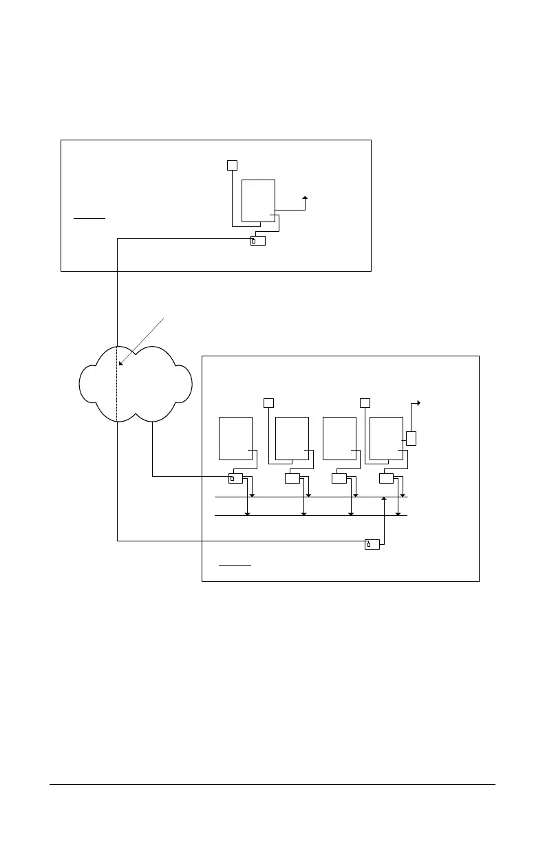
Building 1
Communication Loop - Master
Single ACU panel communication
loop requires only a CIM-LINK
module.
serial or network
connection to PC
with
Communication
Manager
Ethernet
Input A, Input B and Input C programmed to fire the output in Building 2.
Maximum of 2 ACU communication loops may be integrated for global communication
when single ACU communication loop is designated as the master communication loop.
Communication Loop - Subordinate
CAN Bus 2
CIMCIMCIMCIM 0
ACU ACU ACU ACU
All CIMs set as slaves.
Building 2
Input B
Input C
CAN Bus 1
CIM-LINK
J3 ON – Group Master
J4 OFF – Group ACU Mode
Virtual Connection
Output
(Alarm/
CCTV etc.)
OCB-8 or
IOCB1616
CIM-LINK
- communicates with CIM-LINK – Building 2
KI-00487E-10-12
CIM-LINK
- communicates with CIM-LINK – Building 1
See Figure 13 or
Figure 14 for
connections.
See Figure 12 for
connections.