Output noise verification
Periodic and random output deviations superimpose a residual AC voltage on the DC output. This residual voltage is
specified as the rms or peak-to-peak noise in and is specified in the product data sheet.
1.
Turn off the power supply using the AC line switch.
2.
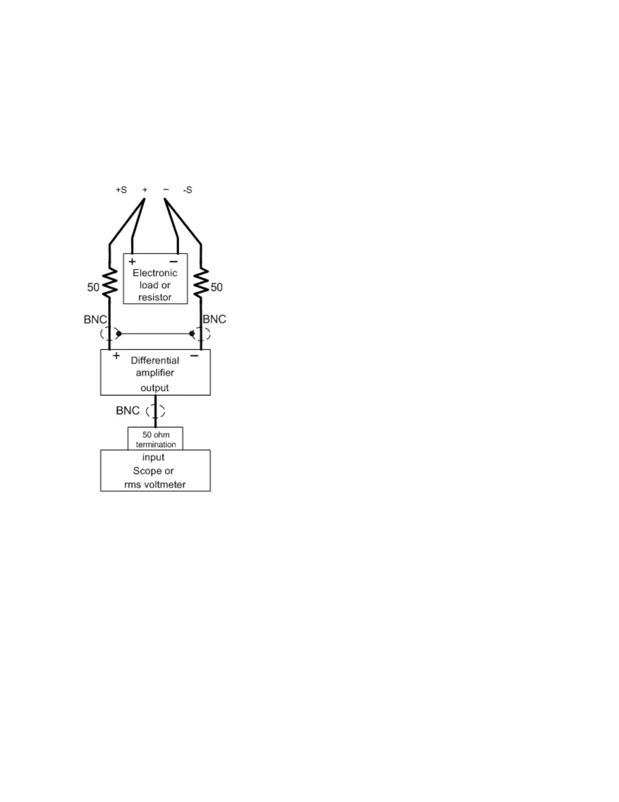
Connect a load resistor or electronic load, differential amplifier, and an oscilloscope (AC coupled) to the output
as shown below.
3.
Use an appropriate load resistor (see load resistor value Recommended test equipment list) to keep the power
system at the instrument setting specified in the test record form under “CV Ripple and Noise”. See the Test
Record Forms under “CV Ripple and Noise” for details.
4.
As shown in the figure, use two BNC cables to connect the differential amplifier to the (+) and (−) output ter-
minals. Each cable should be terminated by a 50 Ω resistor. The shields of the two BNC cables should be con-
nected together. Connect the differential amplifier output to the oscilloscope with a 50 Ω termination at the
oscilloscope input.
5.
Set the differential amplifier to multiply by ten, divide by one, and 1 MΩ input resistance. Set the differential amp-
lifier's positive and negative inputs to AC coupling. Set the oscilloscope’s time base to 5 ms/div, and the vertical
scale to 10 mV/div. Turn the bandwidth limit on (usually 20 or 30 MHz), and set the sampling mode to peak
detect.
Keysight E36100B Series Operating and Service Guide 73