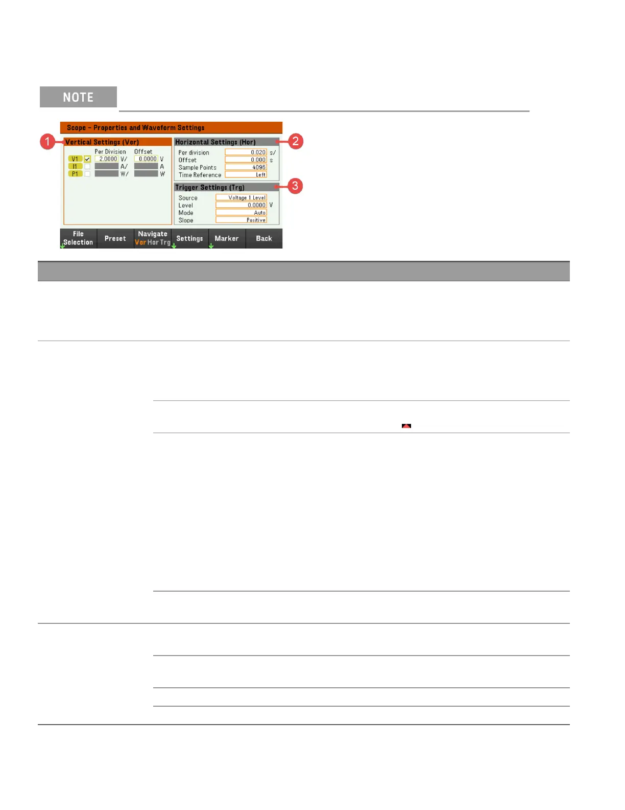
Scope properties and waveform settings
There are no remote interface commands that correspond directly to the front panel Scope functions.
Items Available settings Description
1 Vertical Settings (Ver) Trace checkbox Selects the trace to display for the input. If no checkbox is enabled, no traces will
be displayed for the selected input.
Configures the voltage/division, current/division, power/division and offsets for
each input.
2 Horizontal Settings
(Hor)
Per division Configures to zoom in or out of the data so that you can view waveform details. The
numbers on the top of the display indicate the location of the data that is being
viewed relative to the entire data log. Specified in time/division on the x axis.
Applies to ALL traces.
Offset Configures the waveform location (right or left) of the timebase reference. The trig-
ger point is indicated by the solid arrow .
Sample Points Specifies the number of points in a scope trace. The maximum number of points
that can be specified depends on the number of scope traces that have been
enabled. The minimum number of points that can be specified is 1024.
1 trace enabled: 256 K points
2 traces enabled: 128 K points
4 traces enabled: 64 K points
The power trace counts as 2 traces, since voltage and current must be measured to
calculate power.
If the voltage and current traces have already been selected, the Power trace is not
counted.
Time Reference Specifies the reference point (right, left or center) on the scope display. This is the
position of trigger if no offset has been set.
3 Trigger Settings
(Trg)
Source Specifies a trigger source. This trigger source will trigger the scope measurements
on all input channels.
Level Specifies a trigger level if you select a Voltage level or Current level as the trigger
source.
Mode Specifies a trigger mode.
Slope Specifies a trigger slope.
122
Keysight EL30000 Series User's Guide