Keysight EXG and MXG X-Series Signal Generators User’s Guide 277
Using Custom Digital Modulation for N5172B/82B with Option 431 and 653/655/656/657
Using the Arbitrary Waveform Generator
Configuring the RF Output
1. Set the RF output frequency to 891 MHz.
2. Set the output amplitude to −5 dBm.
3. Press RF On/Off.
The predefined EDGE signal is now available at the signal generator’s RF OUTPUT connector.
Creating a Custom Digital Modulation State
In this procedure, you learn how to set up a single–carrier NADC digital modulation with
customized modulation type, symbol rate, and filtering.
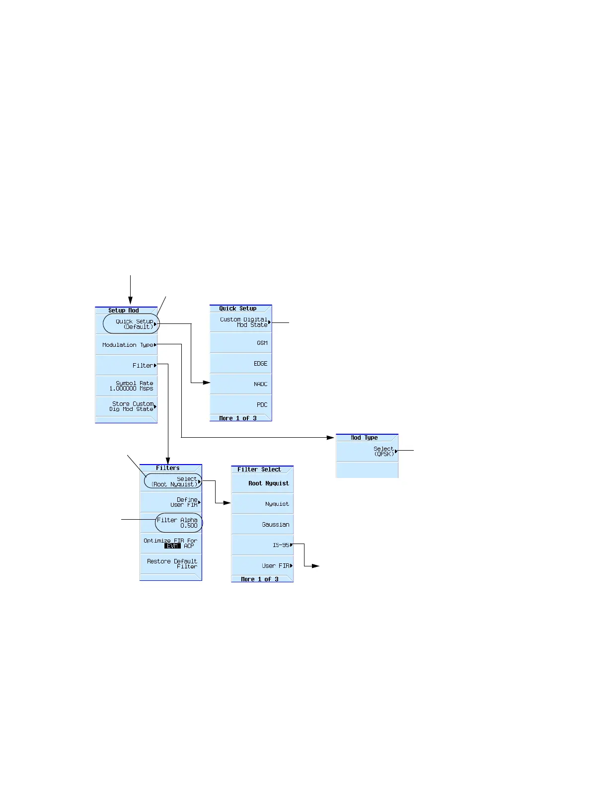
Figure 9-18 Setting a Digital Modulation Filter
This softkey label updates to reflect the
current modulation standard.
Mode > ARB Custom Modulation > Single Carrier Setup
page281
This softkey
sets the filter
bandwidth
parameter,
alpha. The
default Alpha
value changes
with the
modulation
standard (see
page292)
and modulation
type selected
(see
page259).
For details on each key, use key help as described on page56.
This softkey sets
the filter shape.
page278
Opens a menu to select a
IS-95 filter.