Base Matrix Configuration 2
Keysight 34934A User’s Guide 87
Typically, you could make both row and column connections to each module by
fabricating custom cabling terminating in female D-Sub connectors. These attach
to the configuration block’s male D-Sub connectors P1 and P2.
Alternately, you may choose to connect only columns (typically test points on
your DUT) to the D-Subs. There may be physical or electrical advantages in
making your row connections (typically measurement devices) to the
configuration block’s blue extension connectors J3, J4, J5 and J6. To provide this
flexibility, two extension headers are provided on each side of the configuration
block.
You must have set the jumpers (in “Placing Row Extension Jumpers on the
34934C-001 Configuration Block” on page 83) to extend rows to two of the four
headers. We’ll call these the “live” headers.
Had you created two live headers, by performing step 3 on page 81; then the
second header (J3 or J6) on the side selected by jumpers J7 will also be a live
header.
In “Placing Safety Interlock Continuity Jumpers on the 34934C-001 Configuration
Block” on page 85, you will have installed the supplied blue terminators in the live
headers on the configuration block.
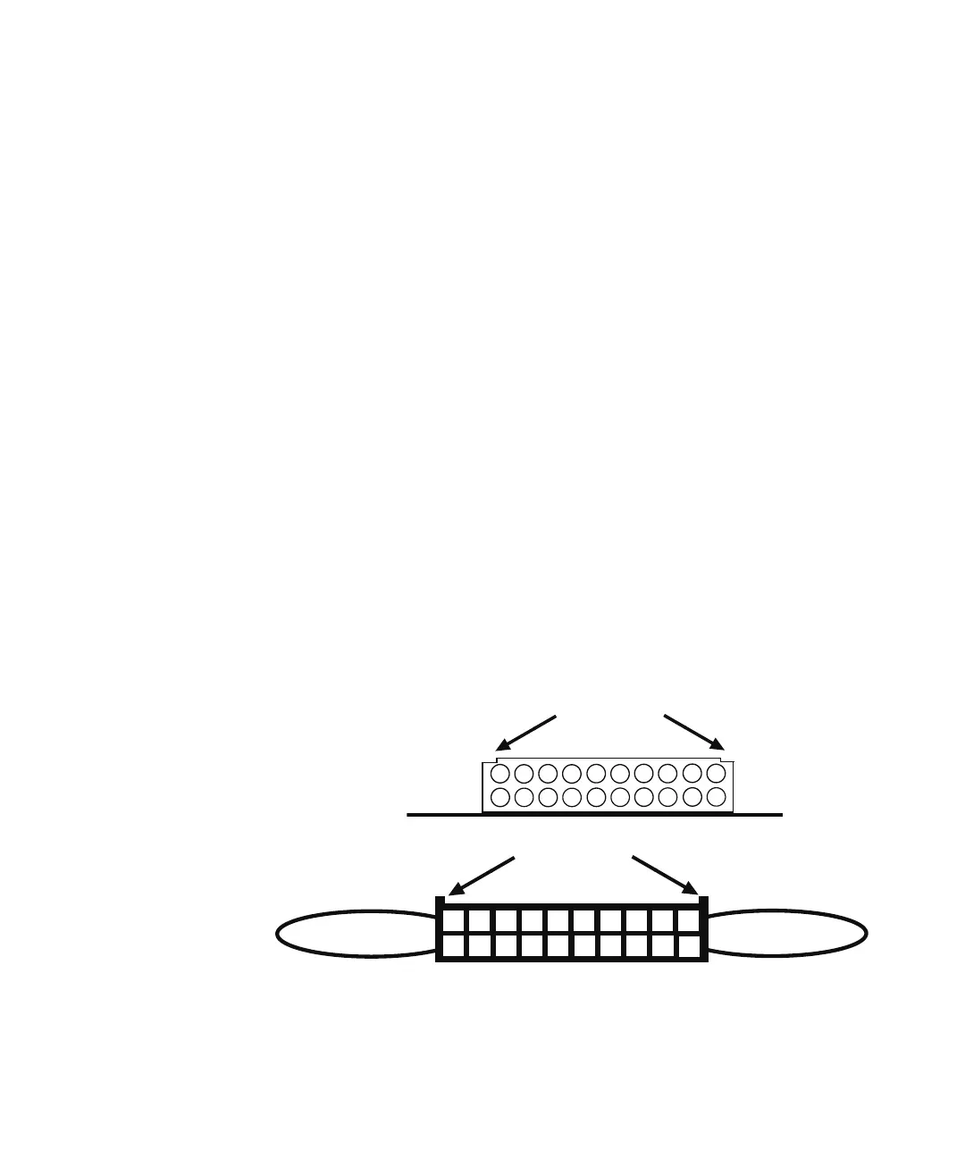
You can now make row connections to these headers, by utilizing the central 16
pins (3-18) on the snap-in terminators. The extension header’s supplied
terminator is shown below. Pay careful attention to the polarizing notches for
identification of pin 1:
182
10
4
6
8
12
14
16
20
1
3
5
7
9
11
13
15
19
17
18
12
14
16
20
2
1
4
3
6
5
8
7
10
9
11
13
15
19
17
Polarizing Notches
circuit board
Extension Headers J3, J4, J5 and J6
Polarizing Notches
Safety Interlock
Terminator for
Pins 19 & 20
Supplied Jumper
from Pin 1-2;
Supplied Extension Terminators