Getting Started Guide 51
Front and Rear Panel Functions
Front Panel Features
Number Item Name Description
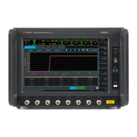
1 Touch-screen LCD Flat-Panel Display with single touch 15” capacitive touch-screen.
2 DisplayPort This is a DisplayPort output, which transfers uncompressed video and audio
data to an external display, such as a PC monitor or projector.
If a monitor is going to be connected to the DisplayPort, it is preferable to make
this connection while instrument power is off. The monitor is normally
detected by the E7515B’s power-on routine; it can sometimes go undetected if
the connection is made after power is on (if that happens, it will be necessary to
cycle power on the E7515B so that the power-on routine is repeated).
3 Front LAN Connection This RJ-45 connector provides front-panel access from the UXM 5G Host PC
enabling a maximum Ethernet data rate of 1 Gigabit. This connector is used for
downloading firmware upgrades, new test platform applications, saving data to
an external memory drive and other reasons for which you may wish to connect
to a local area network and/or to the internet. See
“LAN Connectivity”
on page 39
. The IP address for this input is labeled “Front”.
4 2 - USB Inputs Universal Serial Bus inputs for peripheral devices (mouse, keyboard, flash
drives). These are USB version 2.0. (See the rear panel for USB 3.0 ports.)
5 Power button
Status light
The power button is the On/Off button for AC power. Pressing this button when
the instrument is powered off turns it on. Pressing this button briefly will shut
down the UXM 5G and Windows Operating System safely. (Pressing and
holding this button down for 60 seconds forces a complete instrument
shut-down, but this is not recommended, as it triggers an uncontrolled
Windows shutdown).
The Status light indicates the power status of the instrument (see
“Power
Status Indicator” on page 52
). The line power must be connected in
order for this light to illuminate.
6 -13 RF1 - RF8 Tx/Rx ports
In/Out lights
These ports transmit and receive using the base station emulator of the UXM
5G.
For each port, two indicators are provided; they are lit when the port is
configured to receive (In), to transmit (Out), or to operate in duplex mode
(both).
For ports RF1 through RF8, the maximum RF power input levels are:
+34 dBm MAX CW, +42 dBm MAX Peak, +
20 VDC MAX
Excessive input power can damage the receiver.
See
“Protecting against excessive input power” on page 21.

 Loading...


