5-8 Service Guide N5227-90001
Theory of Operation PNA Series Microwave Network Analyzers
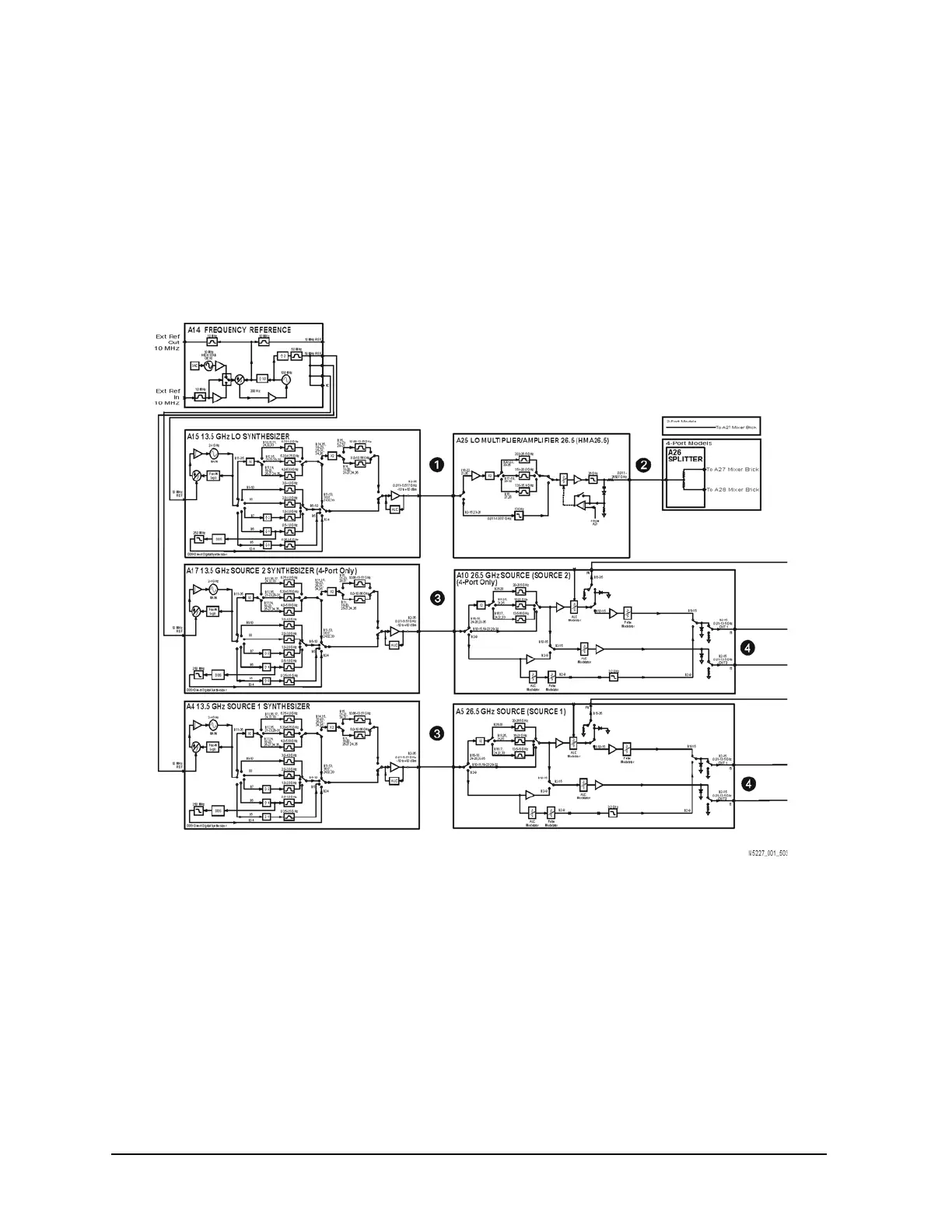
Synthesized Source Group Operation N5227A
The A4, A15, and A17 13.5 GHz synthesizer boards each contain their own phase lock circuitry. The A15
board produces an independently phase locked LO signal while the A4 and A17 boards produce
independently phase locked test signals. This makes it possible for the LO signal to be tuned to a different
frequency than the test signal. With frequency offset mode disabled, the LO signal is 7.438 MHz higher than
the test signal. Since the A4, A15, and A17 13.5 GHz synthesizer boards each receive their 50 MHz input
reference signal from the exact same source, frequency drift error is eliminated.
Figure 5-3 Source Group, Part 1