Sensitivity
The PNA should be located as closely as possible to the test antenna to minimize the RF
cable lengths. The measurement sensitivity of the PNA must be degraded by the inser-
tion loss of the RF cable(s) to determine the system measurement sensitivity needed.
Now, determine the sensitivity required of the PNA
Sensitivity = P
AUT
– DR – S/N – L
where PAUT = Power at the output of the AUT (dBm)
DR = Required dynamic range (dB)
S/N = Signal-to-noise ratio determined above (dB)
L = Cable Loss (dB) from AUT to PNA input
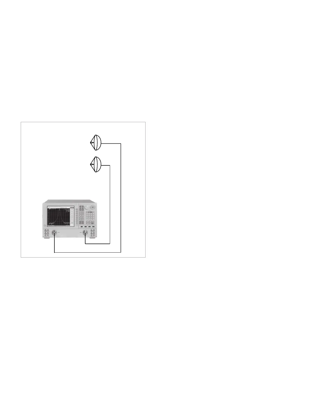
Figure 16. Receive site conguration without external mixing.
Note: This equation assumes the simplest
antenna system with no remote mixing.
See Figure 10.
Receiver #1 Receiver #2
P(AUT)
L
PNA Option 200,
PNA-X Option 200, 020
Reference
27 | Keysight | Antenna Test – Selection Guide

 Loading...


