Multiple-channel measurements
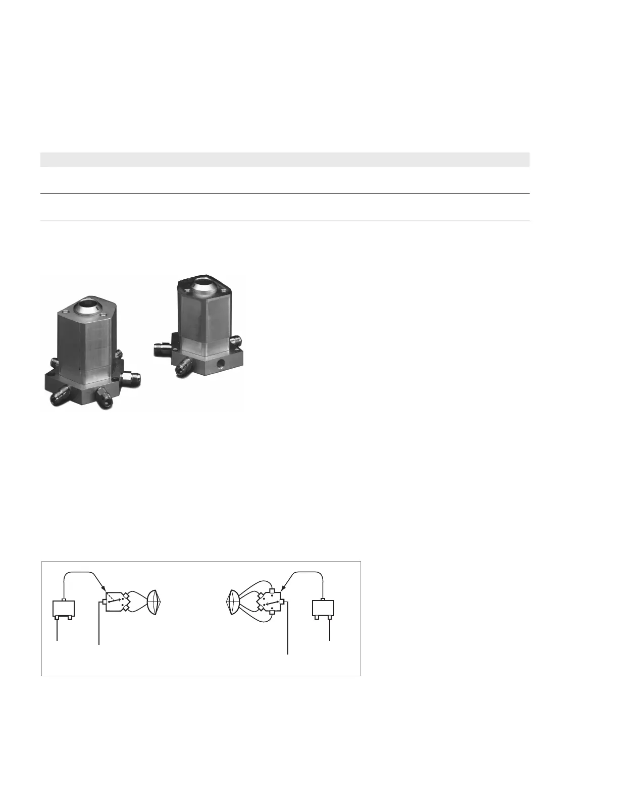
Figure 52. 2 and 4-port PIN switches.
85331B 1P2T PIN switch (0.045 to 50 GHz)
85332B 1P4T PIN switch (0.045 to 50 GHz)
The 85331B and 85332B PIN switches offer the ability to switch between test channels
quickly. These high-performance PIN switches have 90 dB of isolation, low loss, and a
45 MHz to 50 GHz bandwidth. They are absorptive, providing a good impedance match,
which is key to achieving accurate measurements. The switches are small in size and
weather resistant. Figure 52 shows a typical conguration with the PIN switches con-
nected to the source antenna and AUT.
Figure 53. A typical multiple-channel, multiple-frequency system conguration.
Antenna
under test
Switch
control unit
1P4T
PIN switch
Source
antenna
Switch
control unit
1P2T
PIN switch
V
H
To receiver
From transmit source
Note: The 85331B and 85332B do not con-
tain a switch control unit. If your system is
congured with an 85330A multiple channel
controller, the switch control unit must be
ordered separately (Keysight part number
85331-60061)
Recommended power supplies
The 87422A is the recommended power supply for the 83020A amplier. For all other
ampliers, the recommended power supply is the 87421A. A 2-meter power cable with
connectors to connect between amplier and power supply is provided with all power
supplies.
Table 16. Power supply specications
Model ac imput voltage dc output (nom) Output power Sizew (H,W,D)
87421A 100 to 240 VAC
50/60 Hz
+12 V at 2.0 A, –12 V at 200 mA 25 W max 57, 114, 176 mm
2.3, 4.5, 6.9 in
87422A
1
100 to 240 VAC
50/60 Hz
+15 V at 3.3 A, –15 V at 50 mA
+12 V at 2.0 A, –12 V at 200 mA
70 W max 86, 202, 276 mm
3.4, 8.0, 10.9 in
1. The ±15V output is designed to power the 83020A; the ±12V output can be used to power an addi-
tional amplier.
68 | Keysight | Antenna Test – Selection Guide

 Loading...


